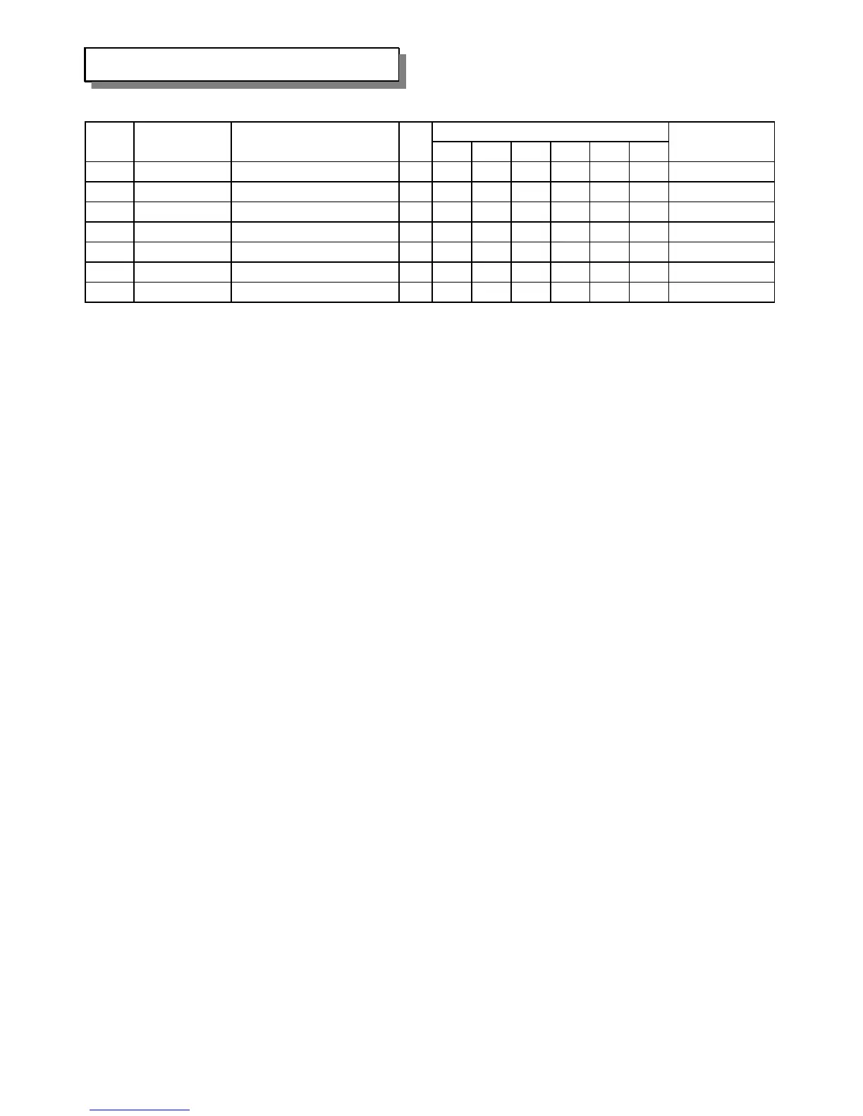
Home
Mitsubishi
Air Conditioner
SRK71ZEA-S1
Mitsubishi SRK71ZEA-S1 User Manual
4
of 1
of 1 rating
106 pages
Give review
Manual
Specs
To Next Page
To Next Page
To Previous Page
To Previous Page
Loading...
SRK63ZEA-S1
Recommendable Purchased Q'ty
10
30
50
100
500
1000
38
RKW129A202
BRACKET MOTOR ( L )
1
1112
39
RKS504A601C
HARNESS ASSY
1
1
1
1
3
1112
FOR FAN MOTOR
40
RKW032A200
PLATE,INSTALLATION
1112
41
RKW129A212
COVER(PIPE)
1
1112
42
RKW132A200
LID(R)
1124
43
RKW132A201
LID(L)
1124
44
SSA913A007A
SCREW,TAP
Note
No.
Part No.
Part Name
RE.Q
‑
85
‑
86
88
Table of Contents
Default Chapter
3
Table of Contents
3
1 General Information
4
Specific Features
4
Fuzzy Control
4
Remote Control Flap & Louver
4
How to Read the Model Name
4
2 Selection Data
5
Specifications
5
Range of Usage & Limitations
7
Exterior Dimensions
7
Piping System
8
Selection Chart
9
Coefficient of Cooling / Heating Capacity in Relation to Temperatures
9
How to Obtain the Cooling and Heating Capacity
9
3 Electrical Data
10
Electrical Wiring
10
4 Outline of Operation Control by Microcomputer
11
Operation Control Function by Remote Control Switch
11
Wireless Remote Control
11
Wired Remote Control
12
Unit ON/OFF Button
13
Power Blackout Auto Restart Function
13
Custom Cord Switching Procedure
14
Flap and Louver Control
14
Modifying the Indoor Unit’s Printed Circuit Board
14
Modifying the Wireless Remote Control
14
Comfortable Timer Setting
15
Sleep Timer Operation
15
Outline of Heating Operation
16
Operation of Major Functional Components in Heating Mode
16
Air Flow Selection
16
Details of Control at each Operation Mode
16
Hot Keep Operation
17
Defrosting Operation
17
Operation of Functional Components During Defrosting Operation
18
Heating “HIGH POWER” Operation
18
Outline of Cooling Operation
19
Operation of Major Functional Components in Cooling Mode
19
Detail of Control in each Mode
19
Cooling Thermostat Operation
19
Outline of Dehumidifying Operation
20
Cooling Oriented Dehumidifying
20
Heating Oriented Dehumidifying
21
Outline of Automatic Operation
21
Determination of Operation Mode
21
Outline of Fan Operation
22
Outline of Clean Operation
22
Outline of Allergen Clear Operation
22
Fan Operation
23
Cooling Operation
23
Heating Cycle Operation
23
ECONOMY Operation
24
Standby Operation
24
External Control (Remote Display)/Control of Input Signal
24
Control of Input Signal
24
Operation Permission/Prohibition Control
25
Protective Control Function
26
Indoor Fan Motor Protection
26
Dew Condensation Prevention Control
26
Detail of Operation
26
Cooling Overload Protective Control
27
Cooling Low Outdoor Temperature Protective Control
27
Reset Conditions
27
High Pressure Control
28
Heating Overload Protective Control
28
Heating Low Outdoor Temperature Protective Control
29
Compressor Protection Start
29
Inching Prevention
29
Low Load Starting
29
Freezing Cycle System Protective Control
30
Prevention of Continuous Low Speed Operation
30
Current Cut
30
Outdoor Unit Failure
30
Power Transistor Overheat Protection
31
Compressor Overheat Protection
31
Serial Signal Transmission Error Protection
31
Compressor Lock
32
Outdoor Fan Motor Protection
32
Stop Mode
32
5 Application Data
33
Safety Precautions
33
Limitations for One Way Piping Length and Vertical
34
Selection of Location for Installation
34
Drilling of Holes and Fixture Sleeve
35
Fixing of Installation Board
35
Installation of Indoor Unit
35
Installing the Support of Piping
36
Mounting of Connecting Wires
36
Preparation of Indoor Unit
36
Top View
36
Drain Hose Changing Procedures
37
Fixing of Indoor Unit
37
How to Remove the Indoor Unit from the Installation Board
37
Indoor Unit Side
38
Installation of Outdoor Unit
38
Outdoor Unit Side
38
Refrigerant Piping
38
Additional Refrigerant Charge
39
Air Purge
39
Insulation of Connecting Portion
39
Test Run
39
Cooling Charactaristics
40
Heating Charactoristics
40
Standard Operation Data
40
Precautions for Wireless Remote Control Installation and Operation
41
When Operating Facing the Air Conditioner
41
Wireless Remote Control Covers the Following Distances
41
Installation of Wired Remote Control and Super Link Adapter (SC-AD-E) (Optional Parts)
42
Installation of Wired Remote Control
43
Recessed Fitting
43
Selection of Installation Location
43
Setting Functions Using the Wired Remote Control
44
Function Setting Method
45
Changing the Remote Control’s Temperature Setting Range
47
Super Link Adapter
48
Wiring Connection Diagram
48
6 Maintenance Data
49
Troubleshooting Procedures for Electrical Equipment
49
Items to Check before Troubleshooting
49
Self-Diagnosis Table
51
Service Mode
52
Explanation of Terms
52
Service Mode Display Procedure
52
Stop Data
54
Remote Control Information Tables
56
Operation Switching
56
Fan Speed Switching
56
Discharge Pipe Temperature Table
58
Service Data Record Form
59
Inspection Procedures Corresponding to Detail of Trouble
60
Sensor Error
60
Discharge Pipe Sensor Temperature Characteristics
60
Indoor Fan Motor Error
60
Abnormality of Outdoor Unit
61
Current Safe Stop
61
Current Cut
61
Over Heat of Compressor
62
Error of Signal Transmission
62
Outdoor Fan Motor Error
63
Rotor Lock
63
Checking the Indoor Electrical Equipment
64
Indoor Unit Circuit Board Check Procedure
64
Indoor Unit Fan Motor Check Procedure
64
Indoor Unit Printed Circuit Board Output Check
64
Inverter Failure Diagnosis
65
Power Transistor Inspection Procedure
67
How to Make Sure of Remote Control
67
Servicing
68
Evacuation
68
Refrigerant Charge
68
Adoption of R410A in Air Conditioners
69
Chemical Characteristics of R410A
69
Chemical Stability
69
7 Refrigerant Piping Installation/Servicing Manual for Air Conditioners Using R410A
69
Safety During Installation/Servicing
70
Lubricating Oils for R410A
70
Refrigerant Piping Installation
70
Piping Materials and Joints Used
70
Joints
71
Flare Joints
71
Socket Joints
71
Flare Processing
72
Dimensions Related to Flare Processing for R410A
72
Dimensions Related to Flare Processing for R22
72
Flare and Flare Nut Dimensions for R410A
72
Flare Connecting Procedures and Precautions
73
Flare and Flare Nut Dimensions for R22
73
Storage of Piping Materials
73
Tightening Torque of Flare for R410A [Reference Values]
73
Identification
74
Precautions before Installation
74
Brazing
74
Processing the Connected Parts
74
Flux
75
Reasons for the Use of Flux
75
Properties Required for Flux
75
Types of Flux
75
Prevention of Oxidation During Brazing
76
Installation, Removal and Servicing
76
Prevention of Overheating
76
Overheating Protection
76
Tools Exclusive for R410A
77
Gauge Manifold
77
Charge Hose
77
Electronic Balance for Refrigerant Charging
77
Vacuum Pump Adapter
78
Refrigerant Cylinder
78
Charge Port and Packing for Refrigerant Cylinder
78
Gas Leakage Detector
78
New Installation Work
79
Air Purge by Vacuum Pump and Gas Leakage Inspection
79
Configuration of Air Purge by Vacuum Pump
79
Replacing the Unit
80
Configuration of Additional Refrigerant Charging
80
Refrigerant Recovery
81
Refrigerant Recharging at Servicing
81
Recovering Procedures
81
Connection of Refrigerant Recovering Equipment
81
Accessories/Tools
82
Cylinder Types
82
Tube Piercing Valve
83
Vacuum Pump
83
Parts List
84
Panel & Fan Assy
85
Heat Exch. & Control
89
4
Based on 1 rating
Ask a question
Give review
Questions and Answers:
Need help?
Do you have a question about the Mitsubishi SRK71ZEA-S1 and is the answer not in the manual?
Ask a question
Mitsubishi SRK71ZEA-S1 Specifications
General
Brand
Mitsubishi
Model
SRK71ZEA-S1
Category
Air Conditioner
Language
English
Related product manuals
Mitsubishi SRK71ZE-S1
23 pages
Mitsubishi SRK71ZM-S
95 pages
Mitsubishi SRK71HE
53 pages
Mitsubishi SRK56A
68 pages
Mitsubishi SRK18CL
44 pages
Mitsubishi SRK52HE
53 pages
Mitsubishi SRK13CES
260 pages
Mitsubishi SRK10CES
260 pages
Mitsubishi SRK25ZJ-S
23 pages
Mitsubishi SRK35ZJ-S
23 pages
Mitsubishi SRK25ZS-S
36 pages
Mitsubishi SRK25ZD-S
69 pages