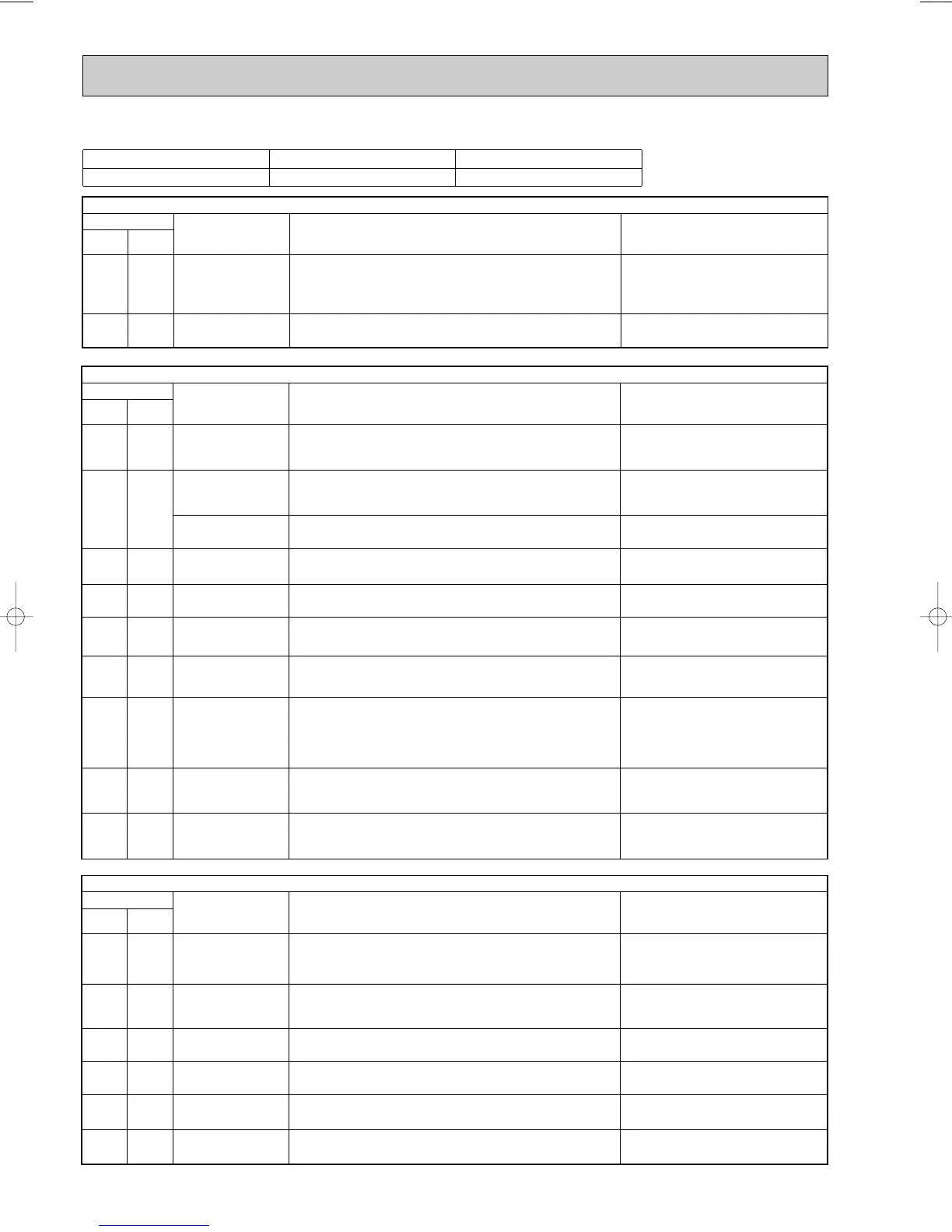
Indication
Abnormal point Detecting method
Symptom: Outdoor unit does not operate.
Check points
LED 1
(Red)
Lighting Twice Outdoor power system
When the compressor operation has been interrupted by over current
protection continuously three times within 1 minute after start-up, or
when power factor control module protection or DC control protection is
activated three times within 3 minutes after the compressor get started.
• Check the inverter/compressor.
• Replace the outdoor electronic control
P.C. board.
Lighting 7 times Outdoor control system
When the nonvolatile memory data cannot be read properly on the
outdoor electronic control P.C. board.
LED 2
(Yellow)
Indication
Abnormal point Detecting method
Symptom: It is repeated that outdoor unit stops and restarts 3 minutes later.
Check points
LED 1
(Red)
Lighting
Outdoor heat exchanger
temperature thermistor
When the outdoor heat exchanger temperature thermistor is short or
open while compressor is operating.
• Replace the outdoor electronic control
P.C. board.
• Check the amount of gas and the
refrigerant cycle.
• Check the outdoor unit air passage.
• Check the characteristic of the discharge
temperature thermistor.
• Check the connector. (CN661)
Lighting 3 times
Discharge temperature
thermistor
When a short or open circuit occurs in the discharge temperature
thermistor during compressor operating.
Twice Goes out
Overcurrent protection When overcurrent is applied to the power module.
3 times Goes out
Discharge temperature
overheat protection
When the discharge temperature thermistor detects 116: or above.
(Protection will be released at 100: or below.)
4 times Goes out
Fin temperature
overheat protection
When the fin temperature thermistor detects 87: or above.
• Check the characteristic of the high
pressure protect thermistor.
• Check the connector. (CN661)
5 times
Lighting Current sensor
When the output from compressor current sensor becomes 25A or
more while the compressor is operating.
• Check if the connection lead wires of com-
pressor are correctly connected.
6 times
• Check if the connection wires between
outdoor electronic control P.C. board and
power board are correctly connected.
Lighting 11 times
Communication error
between P.C. boards
When the communication failure between the outdoor electronic control
P.C. board and power board occurs twice consecutively.
• Check if the connection wires between
noise filter P.C. board and power board are
correctly connected.
Lighting
12 times
Zero cross signal error
When the zero cross signal cannot be detected while the compressor is
operating.
• Check the outdoor unit air passage.
• Check the outdoor fan motor.
• Check the power module.
• Check the inverter/ compressor.
• Check the amount of gas.
• Check the indoor/ outdoor air flow for
short cycle.
• Check the indoor unit air filter for clogging.
• Check the characteristic of the fin
temperature thermistor.
• Check the connector. (CN3)
Lighting 4 times
Fin temperature
thermistor
When a short or open circuit occurs in the fin temperature thermistor
during compressor operating.
P.C. board temperature
thermistor
When a short or open circuit occurs in the P.C. board temperature
thermistor during compressor operating.
LED 2
(Yellow)
Indication
Abnormal point Detecting method
Symptom: It is repeated that outdoor unit stops and restarts 3 minutes later
Check points
LED 1
(Red)
5 times Goes out
High-pressure protection
When the outdoor heat exchanger temperature thermistor detects 69:
or more.
When high-pressure switch detects 4MPa or more. (MUZ-A26YV)
4 times Goes out
P.C. board temperature
overheat protection
When the P.C. board temperature thermistor detects 70: or above.
• Check the outdoor unit air passage.
• Check the outdoor fan motor.
• Replace the outdoor electronic control
P.C. board.
• Check the outdoor unit air passage.
• Check the outdoor fan motor.
8 times Goes out
Power factor control
module protection
When the overcurrent to power factor controller occurs or the output
voltage from power factor controller becomes 400V or more.
• Check the input voltage.
• Check the inverter.
9 times Goes out
DC voltage protection
When it's detected that DC voltage becomes 200V or less, or reaches
400V or more.
• Check the voltage of power supply.
• Check the inverter.
13 times Goes out
Fan motor protection
When the fan motor current is 2A or more, or when the abnormality is
detected in the feedback signal from fan motor.
• Check the outdoor fan motor.
• Check the fan motor connector.
LED 2
(Yellow)
11 times Goes out
Connectivity of indoor
and outdoor unit
When the unusual signal is transmitted from the indoor unit.
• Check if the indoor unit can be connected
with the outdoor unit.
12-2-1. Troubleshooting check table (2)
Refer to page 68.
 Loading...