11
AN T - A
A N T - B
LO O P
OU T
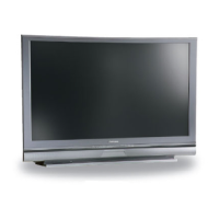
WS-48313, WS-55313, WS-65313
Back Panel
COM PON E NT
480 i / 480P/ 1080i
2
1
Y
P r
Pb
AUD IO -
RI GH T
L E FT /
(
M
O
N
O
)
AUD IO -
Y
G
Pb
B
P r
R
V
H
DTV(Y PbPr/ GBRH V )
48 0 i / 480 P /108 0 i
I N P U T
2
1
AUD I O -
R I G H T
AU DIO-
LEF T /
(MONO)
V I D E O
S-VIDEO
M
O
N
I
T
O
R
OUT
SERVICE WARNING
MONITOR LINK
TM
/DVI
AUDIO-
LEFT/
(MONO)
AUDIO-
RIGHT
CAUTION: TO MEASURE SECOND ANODEVOLTAGE USE A HIGH VOLTAGE METER
CONNECTED FROM ANODE LEAD TOCHASSIS ONLY. DISCHARGE HIGH VOLTAGE TO CHASSIS
ONLY, NOT TO EXTERNAL GROUND.
WARNING: HANDLE WITH CARE HIGH VACUUM PICTURE TUBE IS DANGEROUS TO
HANDLE. REFER SERVICING TO QUALIFIED SERVICE PERSONNEL. REPLACEWITH A TUBE
OF THE SAME TYPE NUMBER FOR CONTINUED SAFETY.
X-RAY PRECAUTION: THIS PRODUCT INCLUDES CRITICAL MECHANICAL AND
ELECTRICAL PARTS WHICH ARE ESSENTIAL FOR X-RADIATION SAFETY. FOR CONTINUED
SAFETY REPLACE CRITICAL COMPONENTS INDICATED IN THE SERVICE MANUAL ONLY WITH
EXACT REPLACEMENT PARTS GIVEN IN THEPARTS LIST. REFER TO SERVICE MANUAL FOR
OPERATING HIGH VOLTAGE AT MINIMUM BRIGHTNESS, MEASUREMENT PROCEDURES AND
PROPER SERVICE ADJUSTMENTS.
1
2
3
4
5
6
7
MONITORLINK
TM
CONTROL
RS-232C
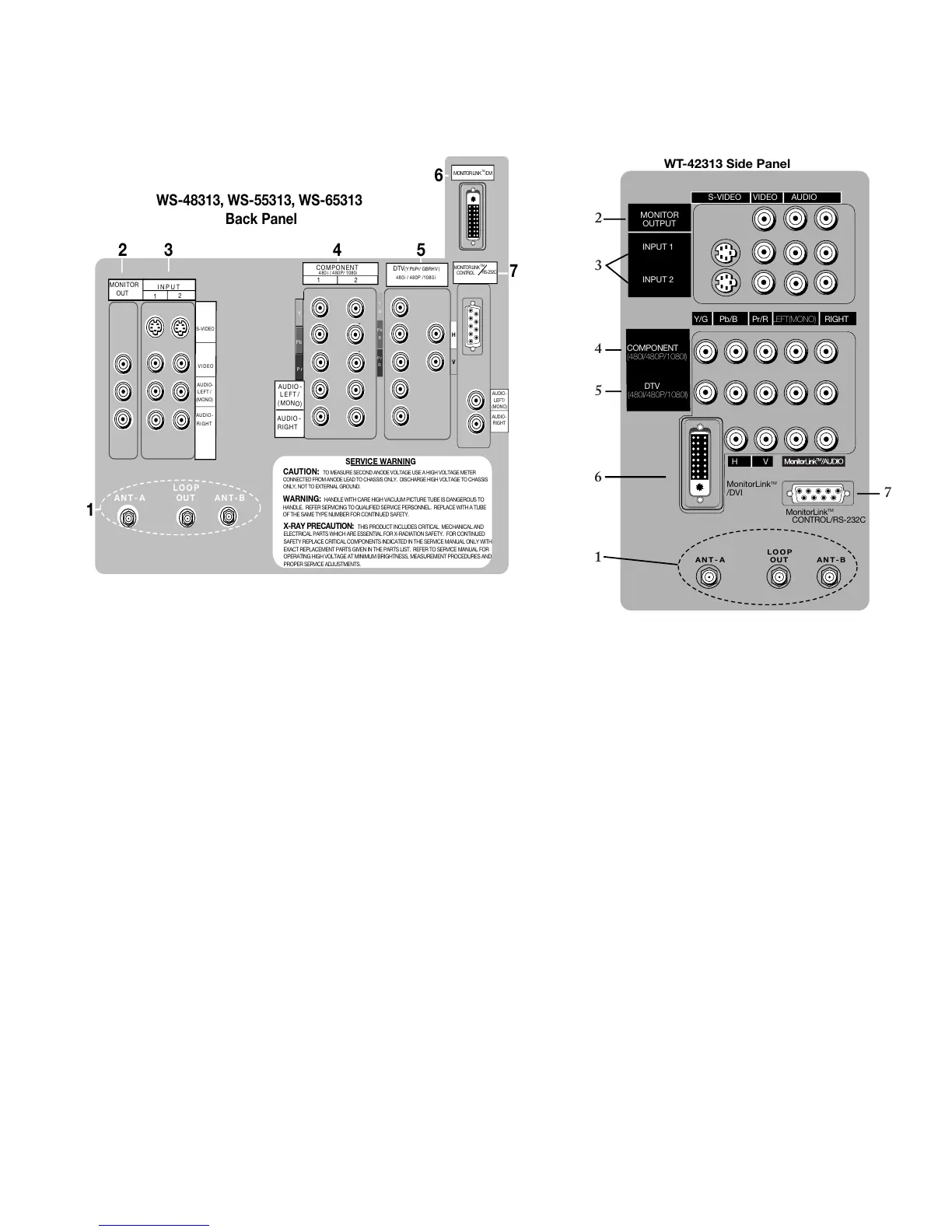
1. ANT-A, LOOP OUT and ANT-B (Antenna)
ANT-A and ANT-B receive signals from VHF/UHF antennas
or a cable system. LOOP OUT sends the ANT-A signal out to
another device, such as a cable box or VCR.
Note: LOOP OUT is disabled when Energy Mode is set to
Low when the TV power is set to Off.
2. Monitor Out
The Monitor Output sends the TV audio and video signals
(excluding component video, DTV video and MonitorLink) to
an A/V receiver or other equipment.
3. Inputs 1-2
These inputs can be used for the connection of a VCR, Super
VHS (S-VHS) VCR, laser disc player, or other A/V device to
the TV. With each input, you may connect to the S-VIDEO
or VIDEO terminal but not to both.
4. Component Inputs 1-2 (Component only for
WT-42313)
These inputs can be used for the connection of A/V equipment
with component video outputs, such as a DVD player or
compatible Video Game System. Please see Appendix B, page
65, for signal compatibility.
Back Panel Input/Output for WS-, WS- & WS-
Side Panel Input/Output for WT-
AN T - A
A N T - B
LO OP
OUT
WT-42313 Side Panel
Y/G Pb/B Pr/R LEFT(MONO) RIGHT
S-VIDEO VIDEO AUDIO
MONITOR
OUTPUT
INPUT 1
INPUT 2
COMPONENT
(480I/480P/1080I)
DTV
(480I/480P/1080I)
H V
MonitorLink
TM
/DVI
MonitorLink
TM
CONTROL/RS-232C
7
1
6
5
4
3
2
5. DTV Input
This input is used to connect a DTV receiver or cable box
and can be configured for HDTV component (YPbPr), or
RGB plus H&V. Please see Appendix B, page 65, for signal
compatibility.
6. MonitorLink™/DVI
This is a Mitsubishi-exclusive proprietary digital interface for
the display of high quality digital video signals from Mitsubishi
products such as the HD-5000 HDTV Receiver/Controller.
All video signals, both analog and digital are sent digitally to
your Mitsubushi TV. Can also be used as a DVI input for
other compatible sources.
Note: The DVI-HDTV input terminal is compliant with the
EIA-861 standard and is not intended for use with personal
computers.
7. MonitorLink™ Control/RS-232C
A digital control interface that works in parallel with
MonitorLink. While MonitorLink provides the digital video
signal, MonitorLink Control provides enhanced functioning
such as automatic power ON/OFF and input selection. Can
also be used with other compatible RS-232C external control
devices.
 Loading...