E
0711
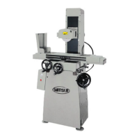
8. OPERATION
A. MOUNTING GRINDING WHEEL TO THE SPINDLE
[ Never depress the push button to turn on the spindle motor
before the flange fastening screw is removed from spindle head to confirm
the rotation direction.
1. Remove the flange fastening screw by clockwise rotation of it.
This screw is threaded opposite the regular thread so that ii will fasten
when spindle is correctly rotating clockwise. (The allow mark on the
wheel cover shows the correct direction.)
2. Turn on the spindle motor by depressing the switch button
(Parts No.19) and confirm it is turning clockwise.
3. If the flange fastening screw is not removed and the rotation is counter-
clockwise, the screw will jump off at tremendous speed and hurt the
machine and even the operator. So. make sure the rotation is clockwise.
If not, check again the wiring and interchange input terminals
R and S. or R and T. or S and T. Interchange of any combination
will reverse the rotation direction.
4. Wheel fastening nut is also reversely threaded. After the flange with
the wheel fastened to it is mounted to the spindle, fasten the flange
to the spindle by the flange fastening screw again.
B. VERTICAL FEED SYSTEM
1. Choice of the right hand screw or left hand screw is available
according to the customer's selection
2. Manual feed of the grinding wheel may be provided by rotation
of the hand wheel.
3. Power elevation (Special execution, see Fig. 20)
a. Turn the selector switch knob above the spindle motor starter
switch to the right for head up. and to the left for
lowering of the head.
— 24 —
 Loading...