CHAPTER 3: USING UNIFLOW
®
2 PROGRAMMING FUNCTIONS
UNIFLOW
®
2 PULSED THERMODE CONTROL
3-10 990-228
SET OUTPUT RELAYS, Page 2
Press the
4 key to bring up the RELAY screen.
The RELAY screen allows you to select the
Alarm for Status actuation states or each relay.
Each relay requires user-provided power, and is
rated for 250 VAC at 5 amps, or 30 VDC at 5
amps.
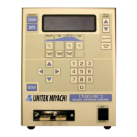
< RELAY >
1. RELAY 1: NC WHEN ALARM
2. RELAY 2: NC WHEN ALARM
3. RELAY 3: NC WHEN ALARM
4. RELAY 4: NC WHEN ALARM
NO=NORMALLY OPEN, NC=NORMALLY CLOSED
NUMBER Select,
Page, Graph or Data
See Appendix B, Electrical and Data Connections for the relay contact pin assignments at Control Status
Connector J6A.
Press the
1 through 4 keys to bring up the desired
relay screen. For example, press
1 to bring up
the
RELAY 1 screen.
Press the 1 key to toggle SET RELAY to between
NC and NO. NC is normally closed, NO is
normally open.
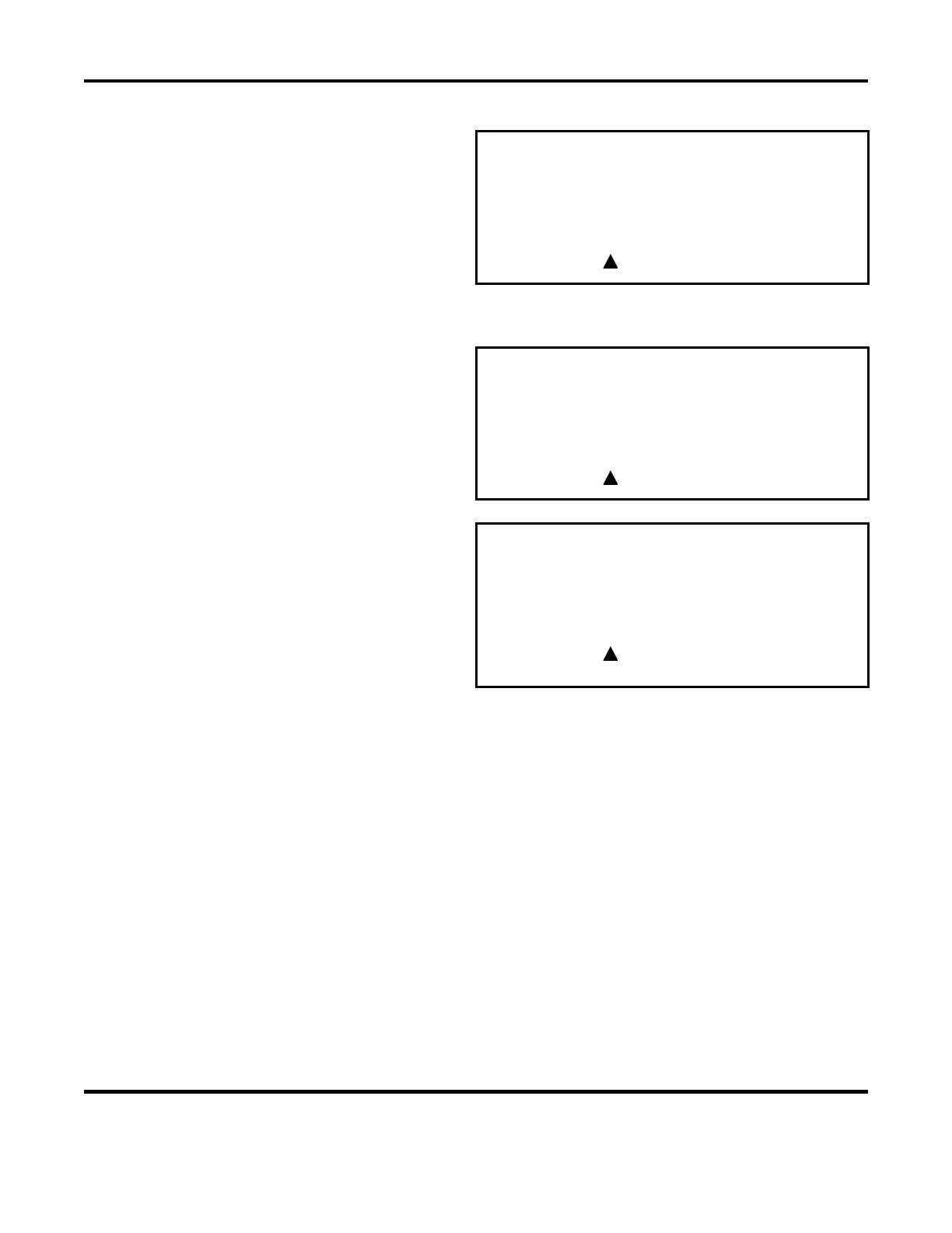
< RELAY 1 >
1. SET RELAY TO : NC
2. WHEN : NOT ACTIVE
NUMBER Select,
Page, Graph or Data
The 2 key will bring up the RELAY 1 status
option screen.
The 1 through 9 keys on the keypad set the
RELAY 1 status options.
1. REFLOW: Relay is NC/NO during the reflow
process cycle.
< RELAY 1 >
1. REFLOW 6. END OF REFLOW
2. PREHEAT ON 7. HEAD IS UP
3. ALARM 8. SYSTEM READY
4. CLEAN THERMODE 9. NOT ACTIVE
5. REPLACE THERMODE
NUMBER Select,
Page, Graph or Data
2. PREHEAT: Relay is NC/NO for continuous preheat.
3. ALARM: Relay is NC/NO for alarm conditions. Auto reset when the alarm clears.
4. CLEAN THERMODE: Relay is NC/NO when the clean thermode counter has expired. Auto reset
when the counter is edited or reset by pushing the zero key at the Graph or Data screen.
5.
REPLACE THERMODE: Relay is NC/NO when the replace thermode counter has expired. Auto reset
when the counter is edited or reset by pushing the zero key at the Graph or Data screen.
6.
END OF REFLOW: Relay is NC/NO when the reflow process cycle has ended. Auto reset at the start
of the next cycle.
7.
HEAD IS UP: Reflow head is in home position.
8. SYSTEM READY: Control is ready for reflow operation.
9. NOT ACTIVE: Relay is not active.
See Appendix B, Electrical and Data Connections for the relay description that includes the timing
diagram showing the sequence of the status options.
 Loading...