Installation
Micro-Ion
®
Module Instruction Manual - 356007-GP 17
Installation Operation MaintenanceBefore You Begin
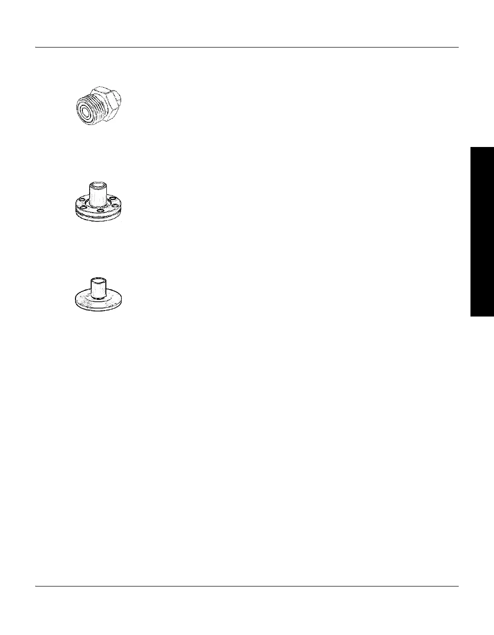
VCR-type fitting a. Remove the plastic or metal bead protector cap from the fitting.
b. If a gasket is used, place the gasket into the female nut.
c. Assemble the components and tighten them finger-tight.
d. While holding a back-up wrench stationary, tighten the female nut 1/8
turn past finger-tight on 316 stainless steel or nickel gaskets, or 1/4 turn
past finger-tight on copper or aluminum gaskets. Do not twist the
module to tighten the fitting.
ConFlat flange To minimize the possibility of leaks with ConFlat flanges, use high strength
stainless steel bolts and a new, clean stainless steel with OFHC copper
gasket. Avoid scratching the seal surfaces.
a. Finger tighten all bolts.
b. Use a wrench to continue tightening 1/8 turn at a time in crisscross
order (1, 4, 2, 5, 3, 6) until flange faces make contact. Further tighten
each bolt about 1/16 turn.
NW flange The NW mounting system requires O-rings and centering rings between
mating flanges.
Tighten the clamp to compress the mating flanges together and seal the
O-ring.
Step 4 Assemble and Connect the Cables
Connecting Cables The cables are user-supplied. Granville-Phillips does not supply cable.
• Use externally shielded cable.
• Connect the wiring to the 9-pin trip point connector and the 15-pin
subminiature D connector. On the User Interface connector, Pin 1 must
be connected to pin 5 for the Micro-Ion gauge to turn ON. See Figure 2-2.

 Loading...

