Chapter 3
26 Micro-Ion
®
Module Instruction Manual - 356007-GP
3.2 Theory of Operation
The Micro-Ion Plus vacuum gauge module consists of two separate pressure
measuring devices: a hot filament Micro-Ion gauge (Bayard-Alpert type
ionization gauge), and a Conductron heat-loss sensor. When power is
applied to the module, the Conductron sensor is ON. As the system is
pumped down, the Conductron sensor turns ON the Micro-Ion gauge at the
pressure switch point. As pressure increases, the Micro-Ion gauge is turned
OFF by the Conductron sensor. The measurement range of the Micro-Ion
gauge and the Conductron sensor overlap. When pressure is within the
measurement range of the gauge and the sensor, the pressure output is a
blended signal in the “transition range” between the gauge and the sensor.
Micro-Ion Gauge
Operation
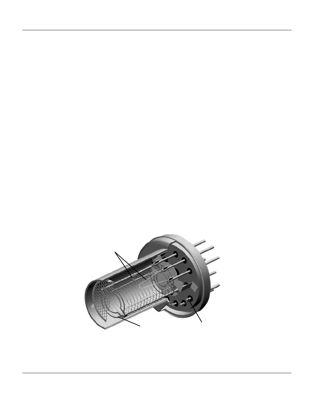
The functional parts of the Micro-Ion gauge are the filaments (cathodes),
grid (anode) and an ion collector, as illustrated in Figure 3-1. These
electrodes are maintained by the controller at +30, +180, and 0 volts,
relative to ground, respectively.
The filaments are heated to such a temperature that electrons are emitted
and accelerated toward the grid by the potential difference between the grid
and filaments. All of the electrons eventually collide with the grid, but many
first traverse the region inside the grid many times.
When an electron collides with a gas molecule, an electron is dislodged
from the molecule, leaving it with a positive charge. Most ions are then
accelerated to the ion collectors. The rate at which electron collisions with
molecules occur is proportional to the density of gas molecules, and hence
the ion current is proportional to the gas density (or pressure, at constant
temperature).
Figure 3-1 Micro-Ion Gauge
Filaments
(+30 V)
Grid (+180 V)
Ion collector (0 V)

 Loading...

