Page|9
41 Daggett Drive, San Jose, CA 95134
Phone: +1 (650) 962 9620 Fax: +1 (650) 962-9647 Email: info@mmr-tech.com Web: www.mmr‐tech.com
GeneralOperation
Theory of Operation
Thesystemdescribedbelow measuresthethermo voltage(SeebeckVoltage)ofmetalsandsemiconductors.
It
alsoprovidestheuserwiththeopportunitytostudythe temperaturedependenceoftheSeebeckVoltage for
different
materials.Below is a pictureof theSeebeck Stagewhich isattached tothe cold stageof theMMR
refrigerator.
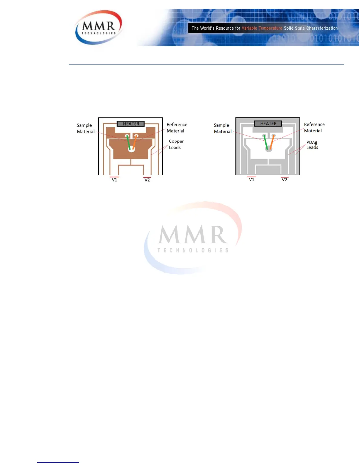
LowTemperatureKaptonStageHighTemperatureCeramicStage
TheoryofOperation
The Seebe ck Stage has two pairs of thermo couples: one of copper and a metal with know n
properties,andtheotherpairofcopperandametalwithproperties tobedetermined.On eofthe
junctionsineach
pairisconsideredareferencejunction,andtheothertheworkingortemperature
modulatedjunction.TheStagealsohasacomputercontrolledheater,locatedclosetotheworking
junctions of each pair, and remote from the reference junctions. This heater is controlled by the
MMRProgrammableSeebeckControllerSB1000.TheSeebeck
stageisattachedtothecoldstage
of an MMR refrigerator, which provides a given stable temperature for the measurement. The
MMRColdstageis controlledbytheMMRK20000DigitalTemperatureController.TheSeebeck
Stagehastwooutputs:V1andV2,whicharemonitoredbyacomputerthrough
theSB1000.
The principle of operation is the following: assume that all four thermocouples are at the same
temperature. Then V1 and V2 will be zero because each member of each pair of thermocouples
compensates the voltage of the other. If power is applied to the heater, then a temperature
difference will be created between the working and the reference junctions because they are
located at different dis tances from the heater. As a result, thermo voltages will be generated in
eachpairgivingnonzerooutputvoltagesVIandV2.Thesearegivenby:
(1).V1=
ε1 ∆T(P)and
(2).V2=
ε2∆T(P)
Where
ε1 and ε2 are the specific thermo‐voltages of the sample and known thermocouples
respectively, and Δ T(P) is the temperature difference between the working and the reference
junctions created by applying power (P) to the computer contr olled heater. We expect, that the
temperaturedifference ΔT(P)willbethe
sameforbothpairsbecausethestagehasasymmetrical
shape.Thevalueofthespecificthermo‐voltageoftheunknownjunctionisthen:
(3).
ε1=ε2V1/V2
 Loading...