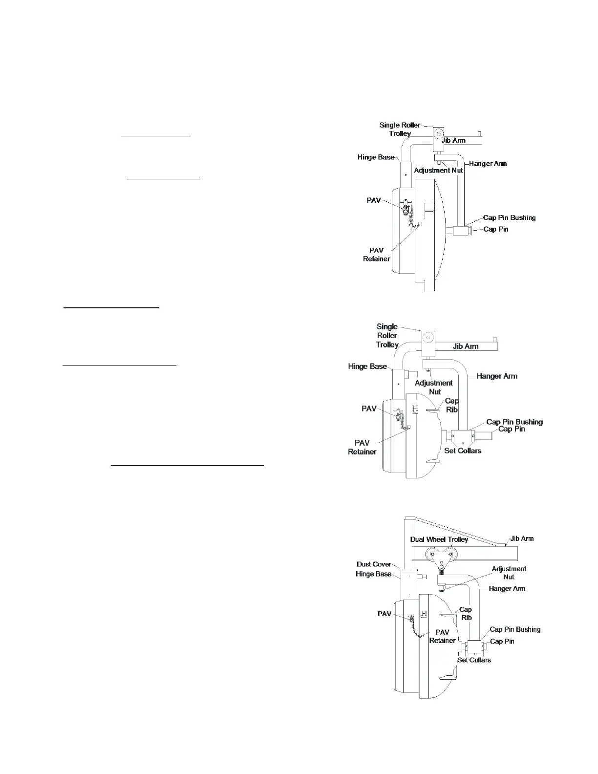
1. If a Pressure Alert Valve (PAV) is present, remove the
stem and screw it into the retainer on the cap.
2. On closures 14” and under, unscrew the cap from the
hub and lift the attached hinge components from
hinge base.
3. On closures 16” and larger, remove the outer set
collar from the cap pin and remove the hanger arm
from the cap pin. Leave the inner set collar in place,
this will retain the parallel balance set by the
manufacturer.
NOTE: A burr may be left behind by the set screw
in the collar. Using a file or emery cloth, remove the
burr to ease removal of the hanger arm and/or
related components.
16” to 24” ANSI 300 class closures are equipped with
a single roller trolley. Slide the hanger arm from the
cap pin and lift the hinge components from the jib
arm.
24” ANSI 600 and larger closures are equipped with a
dual wheel trolley. Measure the distance from the
bottom of the jib arm to the top of the hanger arm, or
put a reference mark on the adjustment bolt above
the hanger arm. Remove the nut, block and hanger
arm from the closure. Do not remove the trolley from
the jib arm.
NOTE: 36” ANSI 600 closures and larger have roller
bearings inside the cap pin bushing. Make sure the
cap pin is free of all burrs to ease removal of the inner
bearing race. Store bearings with care and keep them
protected from dust, grit and other contaminants.
4. Remove the jib arm from the hinge base. The jib
assembly of 24” ANSI 600 and larger closures are
equipped with a brass bushing and tapered roller
bearing inside the hinge base. Take care not to
damage these components. Remove the tapered
bearing race from the bottom of the hinge base.
5. Attach a hook sling to at least three cap ribs. Use the
supplied opening tool to break the seal and loosen
the cap if necessary. Using a crane, continue to
unscrew the cap using just enough lift to keep the cap
floating between threads. Keep lifting and turning till
the cap clears the hub. Place the cap face down on a
clean, flat surface. Plywood or a wooden pallet is
preferred.



 To Next Page
 Loading...