MODERNO IN-WALL/IN-CEILING SPEAKERS
22
INSTALLING THE SPEAKERS
Before Installation: IR Knockout (M6 only)
Moderno M6 speakers have a
knockout for installing an IR
receiver into the speaker’s front
baffle. This allows you to aim
remote controls at the front of
the room instead of at
the electronics, in systems where
the electronics may be placed in
an inconvenient location.
To remove the knockout, drill it
out from the rear using a drill
with a ½” bit (there is a sleeve
guide directly behind the knock-
out).
After inserting the IR receiver
through the hole, seal it into the
speaker using silicone caulk
(make sure that there are no
gaps around the receiver that
could create air leaks) and dress
the cable behind the speaker
along with the speaker wire.
N
OTE
: T
HE SPEAKER
’
S GRILLE MAY
REDUCE THE EFFECTIVENESS OF THE
IR
RECEIVER
. I
FTHISOCCURS
,
SLIGHTLY ENLARGE THE HOLES IN THE
GRILLE THAT ARE DIRECTLY IN FRONT
OF THE
IR
RECEIVER
.
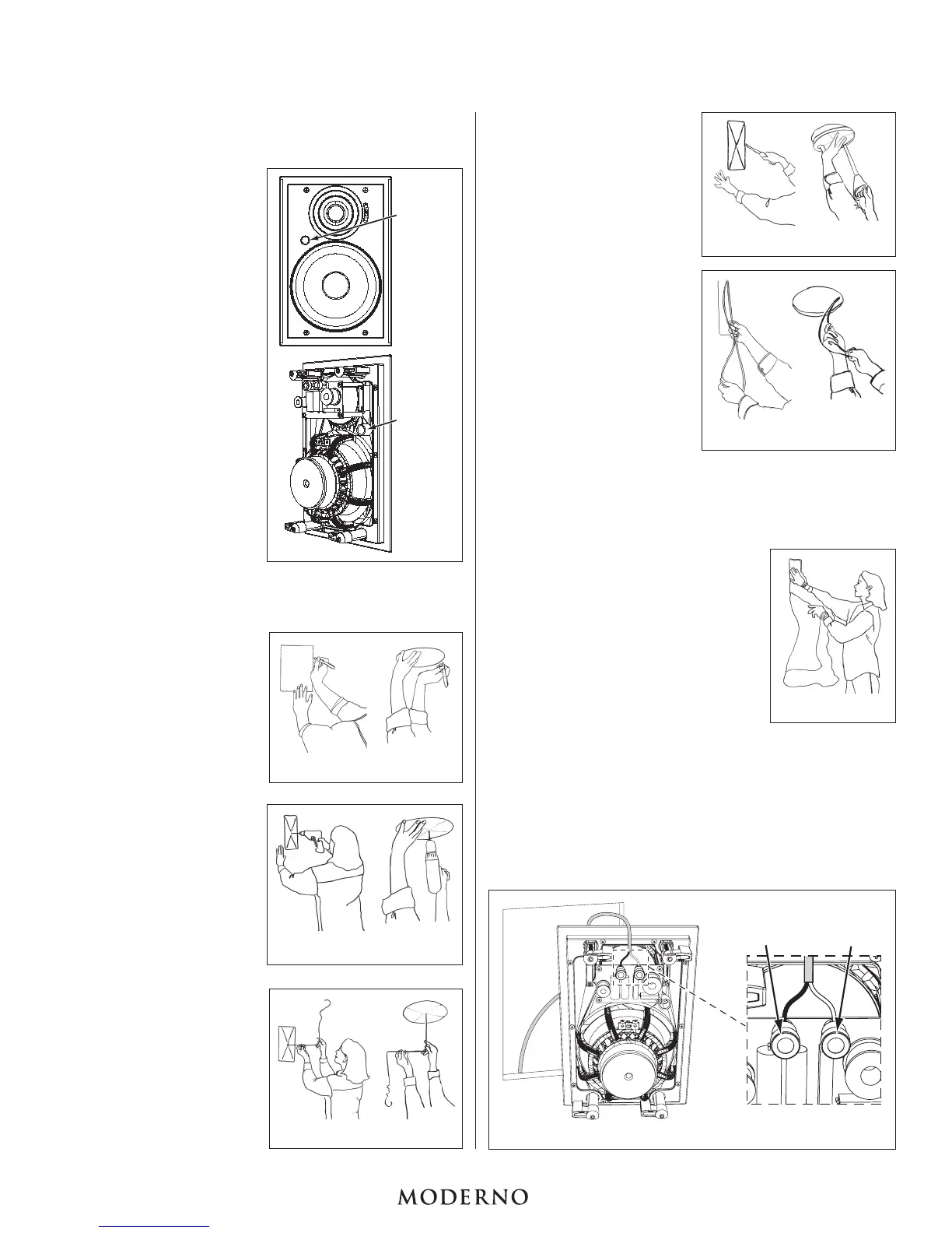
Installing the Speakers
Step 1. Determine the location
for the speaker (see
Speaker Placement
on
page 1). Center the
speaker between the wall
studs or ceiling joists. Tap
the wall or ceiling and lis-
ten for a “hollow” sound,
or use a stud finder to
locate studs.
Step 2. Position the included
cutout template where the
speaker is to be located
and trace the outline on
the wall or ceiling with a
pencil.
• Make sure the speakers
are even with each other
and level.
N
OTE
: R
EAD
S
TEP
6
ABOUT RUNNING
SPEAKER WIRE BEFORE DECIDING ON
THE FINAL SPEAKER LOCATIONS
.
Step 3. Drill a small hole in the
center of the outline you
just traced.
Step 4. Insert a coat hanger wire
into the hole to feel-
around for possible
obstructions. If there are
obstructions, patch the
hole and select another
location for the speaker.
Step 5. Carefully cut the outline
of the mounting hole
using a keyhole or dry-
wall saw. Remove the
drywall from the cutout.
I
MPORTANT: Make sure
your amplifier’s power
is turned off before
performing Step 6.
Step 6. Run the speaker cable
from the speaker outputs
of your amplifier to the
speaker locations. Use
high-quality cable such
as HomeTech HTC100
16/4 cable. Pull the
cables through the
mounting holes you cut in
the wall.
• Allow a few extra feet of
cable, and leave enough
cable slack so you can
strip the insulation from
the conductors when you’re ready to connect to the speakers.
N
OTE
: I
F SPEAKER CABLE IS TO BE RUN THROUGH WALLS OR CEILINGS
,
THE
CABLE
MUST
BE
UL-
AND
CL-
RATED FOR YOUR SAFETY AND BUILDING CODE
COMPLIANCE
.
Step 7. Speaker performance can be
enhanced by insulating the wall or
ceiling cavity with fiberglass
insulation. When insulating speakers,
it is best to use a sheet of unfaced
fiberglass insulation behind and
around the sides of the speaker.
Step 8. Connect the positive (“+”) wire from
the amplifier to the speaker’s red
terminal. Connect the negative (“–”)
wire from the amplifier to the
speaker’s black terminal.
• The speaker’s connector posts are
spring-loaded. Push the top of each connector post down to
open the connector and insert the exposed wires into the
holes in the posts.
IMPORTANT: Be sure not to let any stray ‘+’ and ‘–’
wires touch each other. Touching wires can cause a
short-circuit that could damage your amplifier.
• Double-check that you connected amplifier “+” to speaker
“+” and amplifier “–” to speaker “–”.
 Loading...