10
MoJack EZ Max Lift
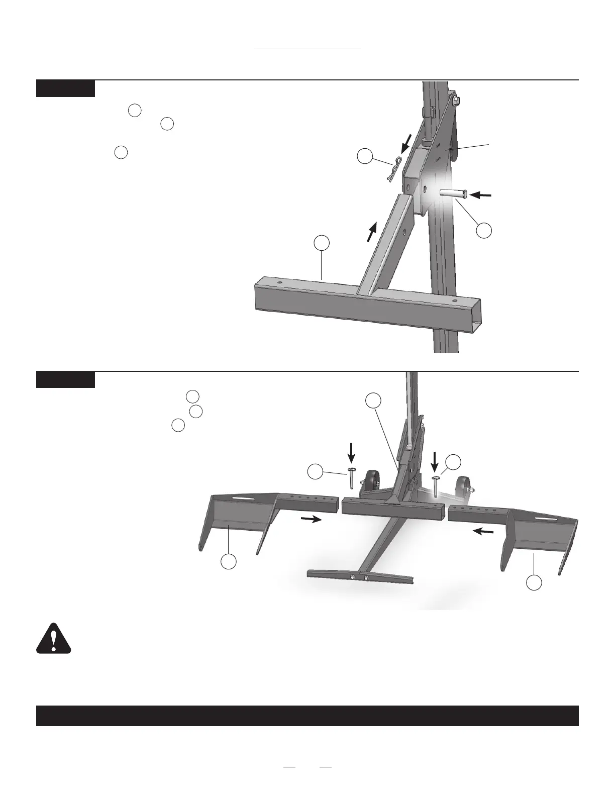
Insert the Lift Arm into the Carrier
and insert the Clevis Pin through
the hole in Carrier and lock by fasten-
ing the Hair Pin to the Clevis Pin.
THIS COMPLETES ASSEMBLY.
STEP 7
2
17
18
Hair Pin
18
Lift Arm
2
Carrier
Clevis Pin
17
Assembly Instructions
Push Pin
16
Lift Arm
2
Wheel Pad Lift Arm
6
STEP 8
Slide the Wheel Pad Lift Arms
onto both sides of the Lift Arm
and secure with Push Pins .
NOTE: The Wheel Pads can be
moved in or out to t different mower
widths. Use the conguration that
works best with your model of lawn
mower.
NOTE: The Safety Straps must
be used during operation
(see Step 9 of the Operating
Instructions).
6
2
16
Push Pin
16
WARNING: Wheel pads must be equal distance from the Lift Arm to maintain proper balance.
For additional information, see see Step 6 of the Operating Instructions.
Wheel Pad Lift Arm
6