G
Lautsprecherleitungen können elektrische Störungen auffan-
gen. Darum sollten sie nur im Abstand von einigen Metern zu
Störquellen (z. B. Dimmer, Lichtschalter) verlegt werden.
G
Verwenden Sie für die Reinigung nur ein trockenes, weiches
Tuch, auf keinen Fall Chemikalien oder Wasser.
G
Wird das Gerät zweckentfremdet, nicht fachgerecht ange-
schlossen oder überlastet, kann keine Haftung für daraus re-
sultierende Sach- oder Personenschäden und keine Garantie
für das Gerät übernommen werden.
3 Elektrischer Anschluss
WARNUNG: Im Betrieb liegt berührungsgefährliche
Spannung bis 100 V an den Anschlüssen an.
Die Installation darf nur durch Fachpersonal erfolgen.
Achten Sie auf die richtige Leistungsanpassung. Eine
Überlastung führt zur Beschädigung der Verstärker-End-
stufe und des 6fach-Lautstärkestellers!
B
Soll das Gerät endgültig aus dem Betrieb genommen
werden, übergeben Sie es zur umweltgerechten Ent-
sorgung einem örtlichen Recyclingbetrieb.
1) Falls die ELA-Anlage eingeschaltet ist, diese zuerst komplett
ausschalten!
2) Die einzelnen Lautstärkesteller entsprechend der Abbildung
an schließen. Zur besseren Handhabung lassen sich die An-
schlussklemmen von ihren Steckverbindungen abziehen.
3) Die Pflichtempfangsrelais (G 1) der einzelnen Lautstärkestel-
ler können durch eine 24-V-Gleichspannung aktiviert werden.
Dadurch sind wichtige Durchsagen über die ELA-Anlage zu
hören, auch wenn ein Lautstärkesteller auf Null steht.
4 Technische Daten
Frequenzbereich: . . . . . . . . . . . 50 – 18 000 Hz
Nennbelastbarkeit
ATT-1935: . . . . . . . . . . . . . . . 6 × 35 W
RMS
ATT-1950: . . . . . . . . . . . . . . . 6 × 50 WRMS
ATT-19100: . . . . . . . . . . . . . . 6 × 100 WRMS
6 × Pflichtempfangsrelais: . . . . . 24 V , 20 mA
Einsatztemperatur: . . . . . . . . . . 0 – 40 °C
Abmessungen (B × H × T): . . . . 482 × 88 × 77 mm, 2 HE
Änderungen vorbehalten.
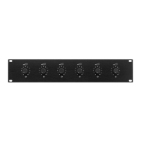
6-way PA Attenuator
Please read these operating instructions carefully prior to instal-
lation and keep them for later reference.
1 Applications
The 6-way attenuator is specially designed for use in PA sys-
tems operating with 100 V technique. The maximum nominal
load for each individual attenuator by the following speak er or by
the following speaker group is as follows:
ATT-1935: 35 W
RMS
ATT-1950: 50 WRMS
ATT-19100: 100 WRMS
The unit is ideally suited for rack installation (482 mm/19"). Two
rack spaces (= 88 mm) are required.
2 Safety Notes
The unit corresponds to all required directives of the EU and is
therefore marked with .
G
The unit is suitable for indoor use only. Protect it against drip-
ping water and splash water, high air humidity, and heat (ad-
missible ambient temperature range 0 – 40 °C).
G
Speaker cables are susceptible to electrical interference.
Therefore, it is recommended to lay them at a distance of sev-
eral metres to sources of interference (e. g. dimmers, light
switches).
G
For cleaning only use a dry, soft cloth; never use chemicals or
water.
G
No guarantee claims for the unit and no liability for any result-
ing personal damage or material damage will be accepted if
the unit is used for other purposes than originally intended, if
it is not connected in an expert way, or if it is overloaded.
3 Electrical Connection
WARNING: During operation, there is a hazard of contact
with a voltage of up to 100 V at the connections.
Installation must be carried out by skilled personnel only.
Pay attention to the correct power matching. An overload
will result in damage of the power amplifier and of the
6-way attenuator!
B
If the unit is to be put out of operation definitively, take
it to a local recycling plant for a disposal which is not
harmful to the environment.
1) If the PA system is switched on, switch it off completely first!
2) Connect the individual attenuators according to the figure. To
facilitate handling, the terminals can be re moved from their
plug-in connections.
3) The emergency priority relays (G 1) of the individual attenu-
ators can be activated by a 24 V DC voltage. Thus, important
announcements can be heard via the PA sys tem, even if an
attenuator is set to zero.
4 Specifications
Frequency range: . . . . . . . . . . . 50 – 18 000 Hz
Power rating
ATT-1935: . . . . . . . . . . . . . . . 6 × 35 W
RMS
ATT-1950: . . . . . . . . . . . . . . . 6 × 50 WRMS
ATT-19100: . . . . . . . . . . . . . . 6 × 100 WRMS
6 × emergency priority relay: . . 24 V , 20 mA
Ambient temperature: . . . . . . . . 0 – 40 °C
Dimensions (W × H × D): . . . . . 482 × 88 × 77 mm,
2 rack spaces
Subject to technical modification.
Atténuateur 6 voies
Public Adress
Veuillez lire la présente notice avec attention avant lʼinstallation
et conservez-la pour pouvoir vous y re porter ultérieurement.
1 Possibilités dʼutilisation
Lʼatténuateur 6 voies Public Adress est spécialement conçu
pour une utilisation dans les systèmes de Public Adress avec
technique ligne 100 V. Chacun des atténuateurs ne doit recevoir
du haut-parleur suivant ou du groupe de haut-parleurs sui-
vants que la puissance nominale maximale suivante :
ATT-1935 : 35 W
RMS
ATT-1950 : 50 WRMS
ATT-19100 : 100 WRMS
Cet appareil est conçu pour une installation en rack 19"/482 mm,
2 unités (= 88 mm) sont nécessaires.
2 Conseils dʼutilisation
Lʼappareil répond à toutes les directives nécessaires de lʼUnion
européenne et porte donc le symbole .
G
Lʼappareil nʼest conçu que pour une utilisation en intérieur.
Protégez-le des éclaboussures, de tout type de projections
dʼeau, de lʼhumidité élevée et de la chaleur (température am-
biante admissible 0 – 40 °C).
G
Les câbles haut-parleurs sont sensibles aux interférences
électriques. Il convient de les placer à une distance de
quelques mètres des sources dʼinterférences (par exemple
dimmers, interrupteurs lumineux).
G
Pour le nettoyage, utilisez un chiffon sec et doux, en aucun
cas de produits chimiques ou dʼeau.
G
Nous déclinons toute responsabilité en cas de dommages
corporels ou matériels résultants si lʼappareil est utilisé dans
un but autre que celui pour lequel il a été conçu, sʼil nʼest pas
correctement branché ou sʼil y a surcharge; de même, la ga-
rantie deviendrait caduque.
3 Branchement électrique
AVERTISSEMENT : pendant le fonctionnement, une ten-
sion de 100 V au plus est présente aux bornes !
Seul un technicien spécialisé est habilité à effectuer lʼins-
tallation.
B
Lorsque lʼappareil est définitivement retiré du service,
vous devez le déposer dans une usine de recyclage de
proximité pour contribuer à son élimination non polluante.
Faites attention à lʼadaptation correcte de la puissance. Une sur-
charge peut endommager l'amplificateur et lʼatténuateur !
1) Si lʼinstallation de Public Adress est allumée, éteignez-la tout
dʼabord complètement.
2) Reliez les atténuateurs individuels selon le schéma. Pour
une meilleure manipulation, il est possible de retirer les
bornes de branchement de leur emplacement.
3) Les relais prioritaires dʼurgence (G 1) de chacun des atténua-
teurs peuvent être activés par une tension continue 24 V. Ainsi,
les annonces importantes sont audibles via lʼinstallation de
Public Adress même si un atténuateur est sur la position zéro.
4 Caractéristiques techniques
Bande passante : . . . . . . . . . . . 50 – 18 000 Hz
Puissance nominale
ATT-1935 : . . . . . . . . . . . . . . 6 × 35 W
RMS
ATT-1950 : . . . . . . . . . . . . . . 6 × 50 WRMS
ATT-19100 : . . . . . . . . . . . . . 6 × 100 WRMS
6 × relais prioritaire : . . . . . . . . . 24 V , 20 mA
Température de fonc. : . . . . . . . 0 – 40 °C
Dimensions (L × H × P) : . . . . . . 482 × 88 × 77 mm, 2 U
Tout droit de modification réservé.
ATT-1935 Best.-Nr. 17.0770
ATT-1950 Best.-Nr. 17.1370
ATT-19100 Best.-Nr. 17.2640