EasyManua.ls Logo

Monicon GTR-205 - User Manual

Monicon GTR-205
21 pages
Print Icon
To Next Page IconTo Next Page
Loading...
GTR-205
Generator Controller
Manual
Web Sitehttp://www.monicon.com.tw
E-mail sales@monicon.com.tw
Question and Answer IconNeed help?

Do you have a question about the Monicon GTR-205 and is the answer not in the manual?

Summary

Introduction to GTR-205 Generator Controller

GTR-205 Generator Controller Features

Analog Display Parameters

Lists analog parameters displayed by the controller, including temperature, pressure, voltage, and current.

Fault and Error Monitoring

Details fault detection capabilities, including specific error types and recorders.

System Operation Buttons

Lists the primary buttons for controlling the generator set's operation modes.

Programmable Front Panel

Highlights the flexibility of the front panel for customization.

Wide DC Power Input Range

Specifies the broad DC voltage range for operation.

Secure Terminal Connector

Describes the terminal connector for secure and easy connection.

Low Power Consumption

Details the controller's energy efficiency in standby mode.

Two-Color Backlight Indicator

Explains the use of backlight for status indication.

High Capacity Output Relays

Mentions the multiple functions and capacity of the output relays.

GTR-205 Technical Specifications

DC Power Input Specification

Details the operational DC voltage input range.

Power Consumption Details

Provides specific power consumption figures at different voltages.

Frequency Measurement Specification

Specifies the range and accuracy for frequency measurement.

DC Voltage Meter Specification

Details the DC voltage measurement range and accuracy.

AC Voltage Meter Specification

Details the AC voltage measurement range and accuracy.

AC Current Meter Specification

Specifies the AC current measurement range via CT ratio and accuracy.

Output Capacity

States the maximum output capacity of the relays.

Operating Temperature Range

Defines the ambient temperature range for operation.

Storage Temperature Range

Defines the ambient temperature range for storage.

GTR-205 Panel Description

Physical Dimensions

Provides the external physical dimensions of the controller.

Panel Cutout Dimensions

Specifies the required dimensions for panel mounting.

Unit Weight

States the weight of the controller unit.

Front Panel View and Layout

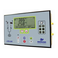
Details the layout and components visible on the front panel.

LED Indicator Lights Explanation

Mains Available LED

Explains the function of the "Mains available" LED.

Generator Available LED

Explains the function of the "Generator available" LED.

Close Mains LED

Describes the "Close Mains" LED status.

Close Generator LED

Describes the "Close Generator" LED status.

Test with Load LED

Explains the "Test with Load" LED function.

LCD Display Screen Layout

LCD Icon and Symbol Glossary

LCD Icon Meanings

Provides a comprehensive explanation of various icons used on the LCD.

LCD Information Displayed

Battery DC Voltage Display

Indicates the display of battery DC voltage.

AC Frequency Display

Indicates the display of AC frequency.

Coolant Temperature Display

Indicates the display of coolant temperature.

Oil Pressure Display

Indicates the display of oil pressure.

Running Hours Display

Indicates the display of total running hours.

Engine RPM Display

Indicates the display of engine speed in RPM.

Gen-set L1-L2 Voltage Display

Indicates the display of L1-L2 gen-set phase voltage.

Gen-set L2-L3 Voltage Display

Indicates the display of L2-L3 gen-set phase voltage.

Gen-set L3-L1 Voltage Display

Indicates the display of L3-L1 gen-set phase voltage.

Gen-set L1 Current Display

Indicates the display of L1 gen-set phase current.

Gen-set L2 Current Display

Indicates the display of L2 gen-set phase current.

Gen-set L3 Current Display

Indicates the display of L3 gen-set phase current.

Gen-set L1-N Voltage Display

Indicates the display of L1-N gen-set phase voltage.

Gen-set L2-N Voltage Display

Indicates the display of L2-N gen-set phase voltage.

Gen-set L3-N Voltage Display

Indicates the display of L3-N gen-set phase voltage.

Utility L1-L2 Voltage Display

Indicates the display of L1-L2 utility phase voltage.

Utility L2-L3 Voltage Display

Indicates the display of L2-L3 utility phase voltage.

Utility L3-L1 Voltage Display

Indicates the display of L3-L1 utility phase voltage.

Utility Frequency Display

Indicates the display of utility frequency.

Error Record Display

Indicates the display of recorded errors.

Start Fail Record Display

Indicates the display of start failure records.

Sum of Starts Record Display

Indicates the display of the total number of engine starts.

Front Panel Button Functions

Plus Button Functionality

Explains the function of the '+' button in different modes.

Minus Button Functionality

Explains the function of the '-' button in different modes.

Up Arrow Button Functionality

Explains the function of the up arrow button in different modes.

Down Arrow Button Functionality

Explains the function of the down arrow button in different modes.

ESC and ENT Button Functionality

ESC Button Functionality

Explains how to enter/exit parameter setting modes.

ENT Button Functionality

Explains the confirmation function of the ENT button.

Code Entry and Parameter Setting Model

Accessing Start and Error Records

Guides on how to view the sum of starts and error records.

Entering Parameter Setting Mode

Entering Parameter Code 0528

Step-by-step guide to enter the '0528' code for settings.

Parameter Setting Navigation (Part I)

Adjusting System Presumption Time

Example of changing a specific parameter (System presumption).

Parameter Setting Navigation (Part II)

Handling Out-of-Range Parameter Settings

Explains how the system alerts for out-of-range parameter values.

General Operation Instructions

Initial Power-Up and Check

Steps to take upon connecting DC power and checking the display.

Default OFF Mode Operation

Describes the default state upon controller startup.

Operation Buttons Explained

Manual Mode Operation (Pre-heat and Start)

Details how to operate the controller in Manual mode, including pre-heat.

AUTO Mode Operation

OFF Mode Operation

Clearing Error Messages

Test with Load Functionality

Nominal Speed and Idle Mode

Detailed Parameter Settings

PARA 01: Stop Duration

Configures the engine stopping time.

PARA 02: Pre-heat Duration

Sets the duration for engine pre-heating before starting.

PARA 03: Crank Attempts

Defines the maximum number of cranking attempts before failure.

More Parameter Settings

PARA 04: Cooling Duration

Sets the duration for generator cooling after stopping.

PARA 05: Idle Time

Configures the duration the engine runs in idle mode.

PARA 06: Low Battery Voltage Setting

Sets the threshold for low battery voltage warning and shutdown.

PARA 07: High Frequency Setting

Sets the threshold for high frequency warning and shutdown.

PARA 08: Function Enable 1

Enables/disables various functions using bit settings.

PARA 09: Low Frequency Setting

Sets the threshold for low frequency warning and shutdown.

Further Parameter Settings

PARA 10: Input Switch Type Selection

Selects the type (NC/NO) for fault input switches.

PARA 11: Oil Pressure Switch Delay

Sets the delay for oil pressure switch activation.

PARA 12: Coolant Temp Sender Brand

Selects the brand for the coolant temperature sensor.

PARA 13: Lubricant Pressure Sender Brand

Selects the brand for the lubricant pressure sensor.

PARA 14: CT Ratio Setting

Configures the Current Transformer ratio for current measurement.

PARA 15: Low Voltage Setting

Sets the threshold for low voltage warning and shutdown.

Additional Parameter Settings

PARA 16: High Voltage Setting

Sets the threshold for high voltage warning and shutdown.

PARA 17: AC Short Setting

Sets the threshold for AC short circuit warning.

PARA 18: AC Overload Setting

Sets the threshold for AC overload warning.

PARA 19: High Water Temperature Setting

Sets the threshold for high coolant temperature warning.

PARA 20: Low Oil Pressure Setting

Sets the threshold for low oil pressure warning.

PARA 21: Enable Functions 2

Enables/disables additional functions using bit settings.

Advanced Parameter Settings

PARA 22: Display Options

Configures display options for various parameters.

PARA 23: Speed Release Motor

Stops the start motor if speed exceeds a set value.

PARA 24: Over Speed Setting

Sets the threshold for over speed warning and shutdown.

PARA 25: Trip-Stop Options

Configures trip or stop actions for various faults.

PARA 26: Fuel Before Start

Setting related to fuel check before starting the engine.

PARA 27: Relay 0 Configuration

Configures the function of Relay 0.

Relay and Code Parameter Settings

PARA 28: Relay 1 Configuration

Configures the function of Relay 1 (Preheat output).

PARA 29: Relay 2 Configuration

Configures the function of Relay 2 (Auto module).

PARA 30: Relay 3 Configuration

Configures the function of Relay 3 (System error).

PARA 31: Relay 4 Configuration

Configures the function of Relay 4 (Gen-set power supply).

PARA 32: Relay 5 Configuration

Configures the function of Relay 5 (Utility power supply).

PARA 33: Parameter Setting Code 1

Sets the first parameter for code entry.

PARA 34: Parameter Setting Code 2

Sets the second parameter for code entry.

PARA 35: Utility Over Voltage

Sets the threshold for utility over voltage warning.

PARA 36: Utility Low Voltage

Sets the threshold for utility low voltage warning.

PARA 37: Utility High Frequency

Sets the threshold for utility high frequency warning.

Utility and Delay Parameter Settings

PARA 38: Utility Low Frequency

Sets the threshold for utility low frequency warning.

PARA 39: Utility Unbalance

Sets the threshold for utility voltage unbalance warning.

PARA 40: Time Delay Emergency Start

Delays emergency start to prevent issues from unstable utility power.

PARA 41: Time Delay Normal to Emergency

Delays switch to emergency power for stability.

PARA 42: Time Delay Emergency to Normal

Delays switch back to utility power to prevent instability.

System Parameter Timings and Actions

Emergency Stop Delay

Sets the delay before an emergency stop action.

Over Frequency Delay

Sets the delay before stopping due to over frequency.

High Coolant Temperature Delay

Sets the delay before stopping due to high coolant temperature.

Low Oil Pressure Delay

Sets the delay before stopping due to low oil pressure.

Low Coolant Level Delay

Sets the delay before stopping due to low coolant level.

Low Frequency Delay

Sets the delay before stopping due to low frequency.

Low Fuel Level Delay

Sets the delay before alarming for low fuel level.

Low Battery Voltage Delay

Sets the delay before alarming for low battery voltage.

Circuit Breaker Closed Delay

Sets the delay for circuit breaker closing action.

Frequency Release Motor Setting

Sets the frequency threshold to release the motor.

Cranking Time

Sets the duration for engine cranking.

Protection Pending Time

Sets a pending time to bypass some fault signals after start.

Back Panel Connector Description

Back Panel Connector Layout

Illustrates the physical layout of connectors on the back panel.

Pin Definitions and Functions

VR Adjustment Functions

VR1: AC Voltage Fine Tuning

Adjusts AC voltage readings for fine-tuning.

VR2: AC Current Fine Tuning

Adjusts AC current readings for fine-tuning.

VR3: Water Temperature Fine Tuning

Adjusts water temperature readings for fine-tuning.

VR4: Oil Pressure Fine Tuning

Adjusts oil pressure readings for fine-tuning.

VR5: Speed Value Fine Tuning

Adjusts speed readings for fine-tuning.

VR6: Speed Value Coarse Tuning

Performs coarse adjustment for speed readings.

Controller Dimensional Drawings

Back View Dimensions

Provides dimensional details for the back of the controller.

Side View Dimensions

Provides dimensional details for the side of the controller.

Top View Dimensions

Provides dimensional details for the top of the controller.

Example Generator Wiring Diagram

Wiring Diagram Details

Illustrates the recommended wiring connections for the controller.

Overview

The GTR-205 is a full digital generator controller designed for comprehensive management and monitoring of gen-sets. It features an LCD panel for displaying error messages, fault input detection, analog signal measurements, and generator status. When an error occurs, the GTR-205 automatically shuts down the engine, and real-time diagnostic information is easily accessible on the LCD panel. Parameters can be adjusted directly from the front panel to meet specific operational requirements.

Function Description

The GTR-205 offers a wide range of functions for controlling and monitoring generator sets:

  • Analog Display: Provides real-time readings for coolant temperature, oil pressure, running hours, frequency, DC voltage, 3-phase AC voltage, and 3-phase AC current, as well as 3-phase grounded AC voltage and utility 3-phase voltage.
  • Fault Monitoring and Display: Detects and displays various fault conditions including over speed (RPM), low frequency, high frequency, high coolant temperature, low oil pressure, over crank, low fuel level, low coolant level, low battery, sensor open, and sensor short. It also records up to 24 errors, start failures, and the total number of starts.
  • System Operation Buttons: Includes dedicated buttons for Off, Auto, Manual, Pre-Heat, Stop, and Run/Idle modes, providing intuitive control over the gen-set.
  • Programmable Front Panel: Allows users to customize parameters and settings directly from the device's front panel.
  • Output Relays: Equipped with 9 output power relays that support multiple functions and are designed to handle heavy power capacities.
  • Parameter Setting: Offers extensive parameter settings for fine-tuning various operational aspects, including stop duration, pre-heat duration, crank attempts, cooling duration, idle time, low battery voltage threshold, high/low frequency settings, input switch types, oil pressure switch delay, sender brand selections (coolant temperature, lubricant pressure), current transformer ratio, high/low voltage settings, AC short/overload settings, high water temperature default, low oil pressure default, and various enable functions.
  • Display Options: Customizable display options allow users to select which parameters are shown on the LCD, such as pick-up/charger alternator, real RPM, PSI/BAR, and °C/°F.
  • Speed Control: Includes settings for speed release motor and over speed thresholds to ensure safe and efficient engine operation.
  • Trip-Stop Options: Configurable trip-stop options for various fault conditions like over load, AC short, low/high voltage, low fuel, and input triggers.
  • Relay Configuration: Allows mapping of various error outputs and operational states to specific relays, providing flexible control over external devices.
  • Utility Monitoring: Monitors utility over voltage, low voltage, high frequency, low frequency, and unbalance conditions, initiating gen-set start-up when utility power is unstable or out of limits.
  • Time Delay Settings: Configurable time delays for emergency start (TDES), normal to emergency switch (TDNE), and emergency to normal switch (TDEN) to prevent unnecessary switching due to temporary utility power fluctuations.

Important Technical Specifications

  • Operational DC Power Input: 8 to 38 V (DC).
  • Power Consumption: Maximum 2 W, 100 mA @ 12 V; 50 mA @ 24 V. Features ultra-low power consumption in standby mode, suitable for small battery chargers.
  • Measured Frequency: Minimum detect volts: 10 V (AC), Range: 0 to 80 Hz, Accuracy: 0.2%.
  • DC Volt Meter: Range: 10 to 31 V, Accuracy: 0.5%.
  • AC Volt Meter: Range: 15 to 512 V, Accuracy: 0.5%.
  • AC Current Meter: Range: Convertible via CT ratio, Accuracy: 0.5%.
  • Output Capacity: 6A / 30 V.
  • Operating Temperature: -30 ℃ to 70 ℃.
  • Storage Temperature: -40 ℃ to 100 ℃.
  • Dimensions: 216 mm × 144 mm × 89 mm.
  • Panel Cutout: 210 mm × 138 mm.
  • Weight: 745 g.
  • Protection Pending Time: 10 seconds (controller bypasses faulty signals, except emergency stop and over speed, after successful gen-set start).

Usage Features

  • User-Friendly Interface: The LCD panel provides clear error messages and status information, making diagnosis straightforward.
  • Easy Parameter Adjustment: Parameters can be adjusted directly from the front panel, eliminating the need for external programming tools for basic configurations.
  • High Security Terminal Connector: Equipped with connectors that allow for easy plug-in and removal, enhancing installation and maintenance convenience.
  • Two-Color Backlight: The LCD features a two-color backlight to easily distinguish system status at a glance.
  • Code Entry Model: A secure code entry system (e.g., "0528") is used to access parameter settings, preventing unauthorized changes.
  • Error Record Access: Users can view a history of continuous failures, total starts, and specific error records (e.g., low frequency) through the code entry model.
  • Parameter Setting Navigation: Intuitive buttons allow users to navigate through parameter setting pages, increase/decrease values, and save configurations.
  • System Presumption: Parameters like stop duration have defined ranges (e.g., 5-40 seconds), and the LCD will display an alarm (e.g., "6E_L" for lower than acceptable, "UP_L" for higher than acceptable) if the set value is outside this range.
  • Operation Modes: Supports Off, Auto, Manual, Pre-Heat, Stop, Run/Idle, and Test with Load modes, covering all typical gen-set operational scenarios.
  • Automatic Operation (AUTO Mode): Automatically detects utility status and decides whether to start the engine. Includes pre-heat indication and handles start failures by returning to pre-heat mode for retry.
  • Manual Operation: Allows manual pre-heat and immediate engine start.
  • Clear Function: Enables clearing of error messages and silencing the buzzer.
  • Test with Load: Initiates engine testing with load, with an option to release the test mode and return to utility power supply.
  • Nominal Speed / Idle Function: Allows switching between nominal speed and idle operation for the generator.

Maintenance Features

  • VR Function (Adjustment for Matching Tolerance): Includes VR1 to VR6 for fine-tuning AC voltage, AC current, water temperature, oil pressure, and speed values. These adjustments help match external and internal measuring meter readouts, ensuring accuracy within 0.5%.
  • Detailed Pin Definition: A comprehensive pin definition list (List 6) is provided for all input and output connections, aiding in wiring and troubleshooting.
  • Error Logging: Records 24 errors, start failures, and total starts, providing valuable data for diagnostics and maintenance planning.
  • Modular Design: The use of high-security terminal connectors simplifies the replacement of components if needed.
  • Wide Operating Temperature Range: Designed to operate reliably in a broad range of environmental conditions, reducing maintenance needs related to temperature extremes.

Monicon GTR-205 Specifications

General IconGeneral
BrandMonicon
ModelGTR-205
CategoryController
LanguageEnglish