16 17
ABOUT ANALOG DELAYS
A delay circuit produces a replica of an audio signal a short time after the
original signal is received. If you listen to the original (direct) signal and the
delayed signal together, the delayed signal will sound like an echo of the
direct. To make a whole series of echoes that die out gradually, you feed
the delayed output signal back to the input. You can determine how far
apart the echoes are by adjusting the delay time of the delay circuit, and
you can adjust how fast the echoes die out by adjusting the amount of
feedback from the delay. In addition, you can determine how loud echoes
are by adjusting the mix between the direct signal and the delayed signal.
During the early 1970s, large-scale semiconductor analog delay circuits
came into being. These are called Bucket Brigade Delay (BBD) chips,
because they function by passing the audio waveform down a chain of
several thousand circuit cells, which is analagous to water being passed by
a bucket brigade to put out a fire. Each cell in the chip introduces a tiny
delay. The total time delay depends on the number of cells and on how
fast the waveform is “clocked”, or moved from one cell to the next.
In the MF-104M, the LFO creates a control voltage that is used to modulate
the time function of the delay. The BBDs in the Delay Line contain 8192
“buckets”. With the time unmodulated the signal spends the same amount
of time in each bucket based on the selected delay time. With the time
modulated by the LFO, the time is no longer constant (or static) and audio
signals already in the buckets get time compressed or stretched. A good
analogy for picturing this is a clock with a sweep hand to show the seconds.
Imagine that you could hold the sweep hand and either slow it down or
speed it up. Yet, when you let it go the sweep hand instantly went to the
correct position on the clock face. In a sense, this is how the LFO
modulates the Delay Line.
In an analog delay the input can be set to saturate gradually, limiting the
maximum signal level and introducing some low level distortion. This actually
enhances the sound quality over what you would have if the MF-104M
produced no distortion whatsoever.
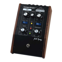
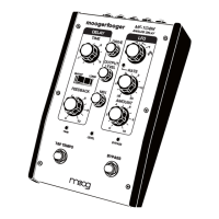
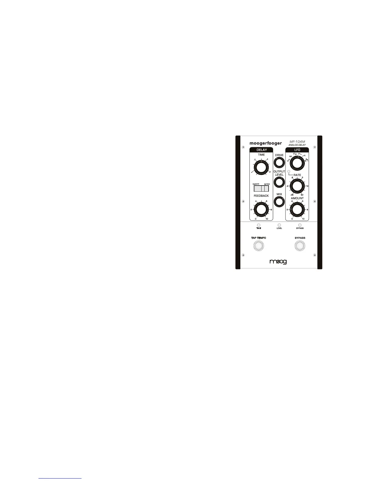
THE MF-104M FRONT PANEL
This section provides more in-depth descriptions of the controls and
indicators on the MF-104M front panel.
MF-104M
ANALOG DELAY
TAP TEMPO
TIME
SHORT LONG
.2
.1
.6
.3
DRIVE CONTROL - Sets the input sensitivity of the Analog Delay. This
control is only active when the effect is ON or in SPILLOVER mode. The
available gain runs approximately 35dB. The Analog Delay is designed to
work with instrument to line-level signals.
LEVEL LED - Works in conjunction with the DRIVE control. Red indicates
clipping. Orange flashes indicate the start of overload. Green indicates the
presence of signal at or below the nominal level.
NOTE: For most instruments, the best approach is to set the DRIVE level so the LEVEL
LED stays consistently green with only peaks in the orange. It is okay to drive the Ana-
log Delay into clipping/distortion if that sound is desired. When using an instrument
with a wide dynamic range, you may want to insert a compressor or limiter prior to
the input of the Analog Delay for the best signal-to-noise ratio without clipping.
 Loading...