Do you have a question about the Motomaster 058-7949-6 and is the answer not in the manual?
Discusses risks of spraying flammable liquids and sparks.
Warns about using the compressor in wet conditions or outdoors when raining.
Covers tank weakening from rust, modifications, and pressure limits.
Advises against operating with shrouds removed due to moving parts.
Warns about hot components like the pump and manifold.
Emphasizes reading paint labels and using respirators.
Recommends safety goggles and avoiding pointing nozzles at people.
Covers daily checks, ventilation, cord protection, and stable operation.
Powers the pump with thermal overload protection and auto reset.
Compresses air into the tank via piston action.
Controls motor start/stop based on tank pressure.
Releases excess pressure to prevent system failure.
Adjusts line pressure to the connected tool.
Indicates the air pressure stored inside the tank.
Shows the pressure delivered to the outlet.
Port for connecting the air hose.
Removes moisture from the tank after shutdown.
Reservoir for storing compressed air.
Connects the unit to a grounded 115-volt circuit.
Describes ideal applications and features like HP motor and tank design.
Guidelines for matching air tools to compressor capacity to avoid issues.
Specifies requirements for using extension cords (wire gauge, length, grounding).
Recommendations for filter-regulators, oiling tools, and connections.
Steps for initial pump break-in, including oiling and running time.
Instructions for unpacking, checking for damage, and verifying contents.
Guidelines for positioning the unit near an outlet and ensuring ventilation.
How to connect an air hose to the compressor outlet.
Importance of using a dedicated circuit for reliable starting and operation.
Steps for starting the compressor for daily use, including checks and startup sequence.
Steps for safely turning off and unplugging the compressor.
Tasks like draining the tank, checking oil, and testing the relief valve.
Cleaning the air filter to maintain performance.
Testing for leaks in connections and hoses.
Procedures for cleaning and protecting the unit when stored for extended periods.
Issues with motor not starting, humming, or running slowly.
Causes for repeated tripping of circuit breakers or blowing fuses.
Problems with the motor running constantly without stopping.
Causes for the regulator not setting or maintaining pressure correctly.
Addresses issues like restricted intake or leaks causing low pressure.
Solutions for excessive moisture in the discharged air.
Details what the 3-year warranty covers and requires.
Lists exclusions and conditions under which warranty is void.
Covers transferability and liability for other damages.
Informs consumers about their specific legal rights and provincial variations.
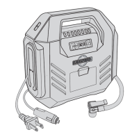
This document serves as the Owner's Manual for the MotoMaster Air Compressor, a 5-gallon unit designed for various applications. It provides essential information regarding the compressor's function, safe operation, maintenance, and troubleshooting. Users are strongly advised to read all safety rules and operating instructions carefully before using the product and to keep this manual for future reference.
The MotoMaster Air Compressor is a robust and versatile tool, ideal for a wide range of automotive applications, from fastening to greasing and engine cleaning. Its design incorporates a 5-gallon twin tank, which is engineered to provide optimum pressure for consistent performance. At its core, the compressor features a 2 HP (peak) induction motor, specifically chosen for its quiet operation, making it suitable for environments where noise reduction is a consideration. The pump is a cast-iron, oil-lubricated unit, contributing to its long-lasting and reliable performance. The compressor comes standard with a 25-foot recoil hose, equipped with a 1/4" NPT connector and a quick connector, facilitating immediate use with compatible air tools.
Key components of the air compressor include an electric motor, an air compressor pump, a pressure switch, a pressure relief valve, an air pressure regulator, a tank pressure gauge, a regulated pressure gauge, an air line outlet, an air tank drain valve, an air tank, and a power cord. The electric motor powers the pump and is equipped with a thermal overload protector with an automatic reset. This safety feature shuts down the motor if it overheats, preventing damage, and automatically restarts once it cools. The air compressor pump is responsible for compressing air and discharging it into the tank through a piston mechanism. The pressure switch, operated manually, controls the motor's start and stop based on the air tank pressure, ensuring it stays within factory-set cut-in and cut-out pressures. It is crucial to set this switch to OFF when the unit is not in use or before unplugging it. The pressure relief valve is a critical safety component designed to prevent system failures by automatically opening to relieve pressure if it exceeds a preset level and the pressure switch fails to shut down the motor. Users can also manually pull the ring on the valve to release pressure. The air pressure regulator allows users to adjust the line pressure to suit the specific requirements of the tool being used, with clockwise rotation increasing pressure and counter-clockwise decreasing it. It is important never to exceed the maximum working pressure of the tool. The tank pressure gauge displays the air pressure stored in the tank and is not adjustable by the operator, nor does it indicate line pressure. The regulated pressure gauge, on the other hand, measures the adjusted outlet pressure. The air line outlet provides the connection point for a 1/4" NPT air hose. The air tank drain valve is used to remove moisture from the air tank after the unit is shut off, a crucial step for preventing rust. The air tank itself stores the compressed air. Finally, the power cord is designed for a nominal 115-volt circuit and requires grounding, emphasizing the importance of connecting it to an outlet with the same configuration as the plug, without using adapters.
For optimal performance and safety, several usage features are highlighted. Users are warned about the risk of explosion or fire, advising against spraying flammable liquids in confined areas, avoiding smoking while spraying, and keeping the compressor away from spraying areas in a well-ventilated space. The risk of electric shock is addressed by requiring wiring to be installed by a licensed electrician and prohibiting outdoor use in wet conditions. To mitigate the risk of bursting, regular draining of condensed water from the tank is essential to prevent rust, and any welding, drilling, or modification of the air tank is strictly forbidden. If a leak is detected, the tank must be replaced immediately. To prevent injury, the compressor must be shut off, unplugged, and all pressure bled from the system before servicing or when not in use. Operating the compressor with shrouds removed is also prohibited due to moving parts. The compressor outlet pressure must always be regulated to not exceed the maximum pressure rating of the tool or accessory. Tampering with the pressure switch or relief valve is strongly discouraged as it can lead to personal injury or property damage. The pump and manifold generate high temperatures, posing a burn risk, so users are advised not to touch these parts while the compressor is running and to allow them to cool before handling. Children should be kept away from the compressor at all times. The risk to breathing when spraying paints or toxic materials necessitates reading all labels, following safety instructions, and using a respirator mask if inhalation is possible. Direct inhalation of compressed air is also warned against. To prevent eye injury, ANSI Z87.1 approved safety goggles must be worn, and no nozzle or sprayer should be pointed at a person or any body part.
Maintenance features are crucial for ensuring the longevity and trouble-free operation of the MotoMaster Air Compressor. Daily checks include pulling the pressure relief valve ring to ensure proper function and clearing obstructions. The air compressor should be located in a well-ventilated area, at least 12 inches (31 cm) from any wall, to facilitate cooling. Protecting the air hose and power cord from damage and puncture, and inspecting them weekly for wear, is also recommended. Hearing protection should always be worn when operating the compressor to prevent hearing loss. The compressor must be operated in a stable position and not on rooftops or elevated positions where it could fall or tip over.
Before initial startup, a break-in period for the pump is required. The pump is shipped without oil, and the provided break-in oil must be poured into the pump through the oil nozzle. The oil level should be checked via the oil sight glass, ensuring it is between the A1 and A2 marks, avoiding overfilling or underfilling. The pressure switch should be turned to OFF, and the tank drain valve opened (counter-clockwise). After plugging in the power cord, the pressure switch is turned ON, allowing the unit to run for 30 minutes to break in internal parts. If issues arise during this period, the unit should be shut down, and Product Service contacted. After 30 minutes, the pressure switch is turned OFF, the tank drain valve closed (clockwise), and then the pressure switch turned ON again. The unit will then fill the tank to cut-out pressure and stop, automatically restarting as compressed air is used. The break-in oil should be changed after 8 hours of operation, and premium compressor oil, SAE 10W-30 all-weather type, is recommended for general use. Used oil must be disposed of in an environmentally friendly manner.
Daily start-up procedures involve checking the oil sight glass, setting the pressure switch to OFF, closing the tank drain valve, and plugging in the power cord. After turning the pressure switch ON, the pressure regulator is adjusted to the desired working pressure for the tool. When adjusting from higher to lower pressure, the knob should be turned counter-clockwise past the desired setting, then clockwise to reach it. The shut-down procedure includes switching the pressure switch to OFF, unplugging the power cord, reducing pressure in the tank via the outlet hose or by pulling the relief valve ring, and opening the drain valve to allow moisture to drain. Caution is advised when opening the drain valve, as escaping air and moisture can propel debris, necessitating safety goggles.
Regular maintenance is crucial. The tank must be drained daily after each workday to prevent corrosion from condensation, especially in cold conditions. The oil level should be checked daily, ensuring it remains within the red circle of the sight glass. The relief valve should be pulled/activated daily to ensure proper function. The air filter needs weekly cleaning to prevent contamination and maintain performance; foam filters can be cleaned with warm, soapy water. Monthly, all connections (tank, hoses, transfer tubes) should be checked for leaks using soapy water; any leaks should be repaired, replaced, or re-sealed without overtightening. For long-term storage, the unit should be cleaned of dust and debris using an air blow gun, the power cord disconnected and coiled, the filter element and housing cleaned, all moisture drained from the tank, and the pressure relief valve pulled to release all pressure. The entire unit should then be covered to protect it from moisture and dust.
The manual also emphasizes the importance of using appropriately matched air tools with the compressor, ensuring the compressor can supply the necessary volume, pressure, and delivery rate without continuous running, as failure to do so may void the warranty. Extension cords should be avoided if possible, but if necessary, a 3-wire, 12 AWG cord no longer than 50 feet (15 m) should be used, plugged into a 3-holed grounded outlet. A longer air hose is preferred over an extension cord. For the air system, a filter-regulator-lubricator is recommended close to the air-powered tool. If not installed, 2-6 drops of compressor oil should be placed into the NPT inlet plug of air-powered tools before each use. A clean air filter is vital for maintaining air pressure and overall performance. Installing a quick connector in the tool and a quick coupler on the hose is advised for better performance. All connections in the air supply system must be sealed to prevent air loss. The compressor should be placed on a hard, level surface to ensure proper moisture drainage and in a clean, well-ventilated area at least 12 inches (31 cm) from any wall. In cold climates, storing portable air compressors in a heated building can reduce issues with motor starting and water condensation. A dedicated circuit is recommended for best performance, as the compressor uses the full capacity of a typical 15 amp household circuit, and other devices drawing power can cause starting failures or motor overload. If a fuse-protected circuit is used, dual element time delay fuses (Buss Fusetron type "T" only) are recommended.
| Power Source | Electric |
|---|---|
| Max Pressure | 125 PSI |
| Type | Portable |
| Voltage | 120V |
| CFM at 90 PSI | 2.6 CFM |
| Motor Power | 1.5 HP |