.F£A:JORES
18 7 6
"'---17
~--12
5
16
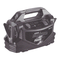
(1). AC/USB slip switch-if the switch is slid to right, the USB port can provide power. If it is
slid to the left, the AC/USB indicator illuminates and both the AC and USB port are
available. If it is at the middle point, both the USB port and AC are off.
(2). USB power port-can provide 5 V 500 mA power.
(3). USB power indicator-if the USB switch is slid to right and there is electricity in the USB
port, this
LED
indicator will illuminate.
(4). AC /USB indicator-indicates both the AC and USB are
available.
(5). Charging indicator-LED indicator, when the battery is being charged, this
LED
indicator will flash green. When the battery is fully charged, this
LED
indicator will light solid
green.
(6). Digital Display-displays the inverter's output power in Wand battery charge status in
%.
(7). Digital Display Button-when pressed, allows for reading Battery Capacity
%
.Toggles
Digital Display's power ON/OFF.
(8). Battery Capacity
%
indicator-illuminates (green) when Battery Charge information is
displayed on the digital display.
(9). Output Power (W) indicator-illuminates (green) when Output Power information is
displayed on the digital display.
(10). Correct connection indicator-a green
LED
indicator. When the clamps are connected
to the battery correctly, with the red clamp to the positive and black clamp to the
negative,
this
LED
will light.
6.
 Loading...