Chapter 6 Finishing the Installation
6.1 Cable Connection
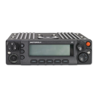
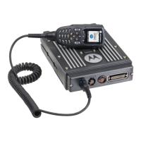
6.1.1 O9 Control Head
Perform the following if it has not been previously done:
1. Remove the control head from its mounting trunnion. Plug the radio's CAN cable into the
proper location on the back of the control head (see Figure 2-22 and Figure 2-24 in
Chapter 2). The connectors “click” when snapped into place. The control head model can
have the microphone plugged into the CGAI connection on the control head back panel.
2. Connect the plug from the speaker lead to the mating connector coming out of the power
cable.
3. Plug the VIP connector into the correct location on the back of the control head.
4. Connect the CAN cable to the proper location on the transceiver.
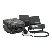
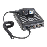
6.1.2 O5 Control Head
Perform the following if it has not been previously done:
1. Remove the control head from its mounting trunnion. Plug the radio's CAN cable into the
proper location on the back of the control head (see Figure 2-21 and Figure 2-23 in
Chapter 2). The connectors “click” when snapped into place. The control head model can
have the microphone plugged into the lower left corner of the control head front panel.
2. Connect the plug from the speaker lead to the mating connector coming out of the power
cable.
3. Plug the VIP connector into the correct location on the back of the control head.
4. Connect the CAN cable to the proper location on the transceiver.
 Loading...