6
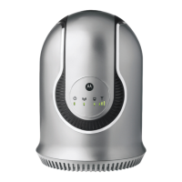
Desktop CPEi 300 User Guide
Back of CPE
The back of the CPE unit contains the reset switch, AC Power
Connector, Ethernet connector, Line 1 and Line 2 telephone ports,
and the External Antenna Connector (accessory available from your
service provider).
Back of the Unit
Port Descriptions
Back Panel Ports Description
External Antenna External Antenna Connector
Ethernet Ethernet Port
Power AC Power Connector
Reset
Note:
Hardware Reset Button (A
paperclip is recommended for accessing
this button). Before resetting the CPE,
ensure the power LED is ON.
Phone Line 1 RJ-11 port for use with VoIP.
Phone Line 2 RJ-11 port for use with VoIP.
 Loading...