2-1
Section 2
UHF1 PCB/SCHEMATICS/PARTS LIST
1.0 Allocation of Schematics and Circuit Boards
1.1 UHF1 25W Circuits
The UHF1 circuits are contained on the Printed Circuit Board (PCB) which also contains the
Controller circuits. This chapter shows the schematics for the UHF1 25W circuits only, refer to the
Controller section for details of the related Controller circuits. The PCB component layouts and the
Parts List in this chapter show both the Controller and UHF1 25W circuit components. The UHF1
25W schematics and the related PCB and parts list are shown in the table below
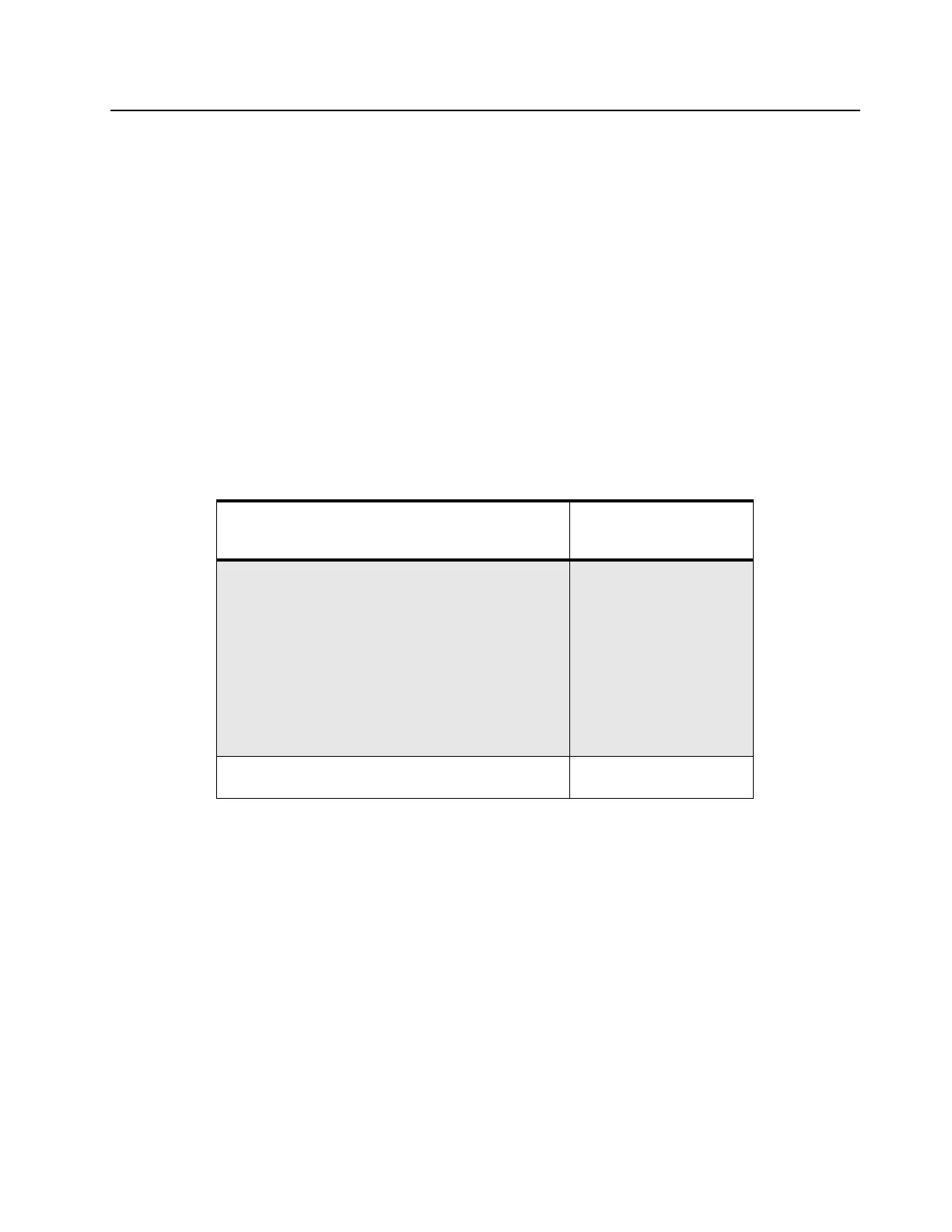
Table 2-1 UHF1 1–25W Schematic Diagrams and Parts List
PCB :
84012735001-A Main Board Top Side
84012735001-A Main Board Bottom Side
Page 2-3
Page 2-4
SCHEMATICS
Overall
Receiver Front- End
Receiver IF Amp
Transmitter Power Amplifier
Power Control
Transmitter Power Amplifier DC Distribution
RFIC
Receiver VCO
Transmit VCO
VCO Buffer
Page 2-5
Page 2-6
Page 2-7
Page 2-8
Page 2-9
Page 2-10
Page 2-11
Page 2-12
Page 2-13
Page 2-14
Parts List
84012735001-A (UHF1 25W Only) Page 2-15
 Loading...

