Do you have a question about the Motorola MT500 H23BBB and is the answer not in the manual?
Details of the radio's transmission capabilities and specifications.
Details of the radio's reception capabilities and specifications.
Covers "Private-Line", Selective Call, Single-tone, Time-Out Timer, and Interference protection.
Explains Tone PL, Digital PL, Selective Call, Group Call, and Subaudible coding.
Details on rechargeable and mercury batteries, and their properties.
Details on turning on, setting volume, squelch, and transmitting.
Details the tone PL circuit for decoding subaudible tones.
Explains the digital coded squelch system.
Transmits identifying code and emergency status to base station.
Details on Ni-Cad, Mercury, and other batteries, plus their characteristics.
Covers VHF RF, UHF RF, IF, and Audio circuits.
Explains the squelch operation and circuitry.
Details the RF section of VHF receivers.
Details the RF section of UHF receivers.
Explains the operation of the emergency call feature.
Description of the transmit power amplifier module.
Description of the IDC module for audio processing.
Guidelines for replacing components and modules.
Lists required test equipment and their applications.
Safety precautions for handling MOS devices.
Procedures for diagnosing excessive current drain.
Troubleshooting steps for sensitivity issues.
Analysis of RF portion performance via noise measurements.
Troubleshooting RF front end for VHF and UHF radios.
Troubleshooting for squelch issues.
Troubleshooting steps for low or no transmit power.
Troubleshooting steps for low or no transmit power.
Instructions for replacing discrete components.
Instructions for replacing hybrid modules.
| Number of Channels | 16 |
|---|---|
| Waterproof Rating | IP54 |
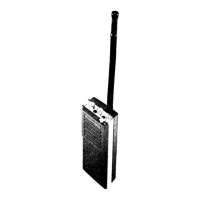
| Type | Portable Two-Way Radio |
| Channel Spacing | 12.5/25 kHz |
| Model | MT500 H23BBB |