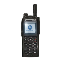
5.1 - 2 MTP850 TETRA Handportable Terminal / Basic Service Manual TEST SETUP & TESTING 380–430MHz
Connect the red (+) and black (-) wires of the battery eliminator to the
respective positive and negative points of the power supply, and use the
correct voltage (3.8VDC, max. 4.2VDC). Neglecting this would damage your
radio and/or the power supply.
Figure 1 Typical Test Setup
Alternative Test Setup
Cable adapter 2888482K04 enables connecting to the vehicle adapter connector
on a stand-alone main board. Thus, it allows testing of the main board in a
disassembled unit. On one side, the cable adapter has a mating vehicle adapter
connector with mechanical grasping mechanism; on the other side the
connection is SMA male.
IFR 2968
RF CABLE
(3086228J02)
N-TYPE
RF CONNECTOR
POWER
SUPPLY
3.8 V
MTP850
BATTERY
ELIMINATOR*

 Loading...
