16 MW810 Mobile Workstation Vehicle Installation Manual
Step 2. If screws and nuts are used for anchoring the mount, mark the hole locations using the
base of the mount and drill four 5.5 mm holes into the dashboard.
Step 3. If self-tapping screws are used for anchoring the mount, attach the mount to the
desi
red location and drive the screws into the dashboard.
Step 4. Connect the display to the VESA Plate and secure using four screws and washers.
Step 5. Connect the display signal
cabl
e and the power cable
to the display.
Step 6. Using four screws, install
th
e display to the pedestal
Mount.
Step 7. Adjust the display position.
Step 8. Route the Display Signal
and Powe
r cables down to
the CPU Box. Ensure that
the cables have enough
slack to move when the
display is tilted up/down or
swiveled.
For cable connections, refer to
s
t
eps 5 to 7 of “To Assumable and
Install the Display DIN Mount,
perform the following steps (see
Figure 15):” on page 19.
Be careful not to drill or drive screws into wires, circuits or
equipment located under the dashboard
The pedestal mount can be assembled to the VESA plate on
bot
h of it's base end sides.
It is very important to use spring washers when securing the
di
splay to the Display Bracket.
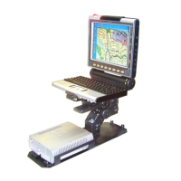
Figure 12
8.4” Display - Free-standing pedestal mount
VESA Plate
0.22” D Screw Hole
M4, 16 Screw

 Loading...