20 MW810 Mobile Workstation Vehicle Installation Manual
Step 5. Plug the connector of the display signal cable and use the three screws to secure the
connector to the display.
Step 6.
Note that cables are available with right-side or left-side display exit for right-side or
left-side driver seat position.
Step 7. Plug the keyboard cable to the USB port and secure the cable to the display by using
t
he t
humb screws.
Step 8. Plug the power cable to the power connector on the back of the display.
Use caution when connecting the display to CPU cable. Rough
installation may damage the connectors/receptacles of the display,
cable or CPU Box.
To avoid damage to the display and CPU Box, verify that the Main
Po
wer
switch, located on the back panel of the CPU Box, is turned Off
before connecting cables to the display.
The maximum current load from USB 2.0 port is 500mA.
Use the rubber plug, provided with this product, to seal the port when
not in
use.
The display is powered directly from the vehicle power system. The
disp
lay software uses power management tools to prevent excessive
battery drainage during normal operation and vehicle start.
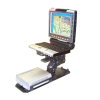
Figure 16
8.4” Display - Installation of Cables
VESA Plate
Keyboard Cable to USB 2.0 Port
Side Screws
Center Screw
Center Screw Hole
Swivel Bracket
Power Cable
Display Signal Cable
USB 2.0
Port for
Temp or ary
Connection
of Devices
15A SB Fuse
Use Cable Clamp
F
i
lt
e
r
s
Power Connector
USB 2.0 Port
for keyboard

 Loading...