List of Figures
x
List of Figures
Figure 1 - Typical PTP 500 Series Bridge Deployment........................................................................ 13
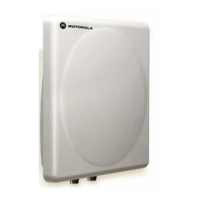
Figure 2 – PTP 500 Series Bridge Outdoor Unit (ODU)....................................................................... 15
Figure 3 - Power Indoor Unit (PIDU Plus PTP 300/500/600 Series).................................................... 16
Figure 4 – PIDU Plus Recovery Switch Location ................................................................................. 17
Figure 5 – PIDU Plus Power Input........................................................................................................ 18
Figure 6 - External DC Supply Only ..................................................................................................... 19
Figure 7 - External DC Supply and AC Supply..................................................................................... 19
Figure 8 - External DC Supply and Redundant AC Supply .................................................................. 19
Figure 9 - Remote LED and Recovery Switch Wiring .......................................................................... 20
Figure 10 – PTP 500 Series Bridge Layer Diagram ............................................................................. 24
Figure 11 - 5.8 GHz UK RTTT Channel Avoidance – 15 MHz Channel Bandwidth (Example)........... 31
Figure 12 - ODU mounted in Zones A & B ........................................................................................... 40
Figure 13 – Using a Finial to Extend Zone B........................................................................................ 41
Figure 14 – PTP LPU Installation Example for PTP 500 Series (Not to Scale) ................................... 42
Figure 15 - PTP LPU Full Kit ................................................................................................................ 43
Figure 16 - Simplified Circuit Diagram.................................................................................................. 44
Figure 17 - Typical Mast or Wall Installations....................................................................................... 46
Figure 18 – ODU with Mounting Bracket and Earth Bonding Lead...................................................... 49
Figure 19 – ODU Bracket Strap............................................................................................................ 50
Figure 20 – ODU Mounting Bracket ..................................................................................................... 50
Figure 21 - ODU Mounted on Pole....................................................................................................... 51
Figure 22 - Integral Safety Loop ........................................................................................................... 52
Figure 23 - Correct Cable Preparation for the Recommended Cable .................................................. 54
Figure 24 - Completed ODU Connector ............................................................................................... 55
Figure 25 - Correct and Incorrect Tightening of Cable Gland .............................................................. 55
Figure 26 – ODU PIDU Plus Connexion............................................................................................... 56

 Loading...