6 7
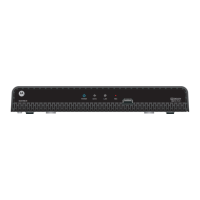
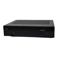
Rear panel
The marking plate is located
on exterior of the bottom of
the apparatus.
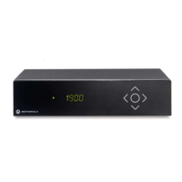
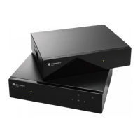
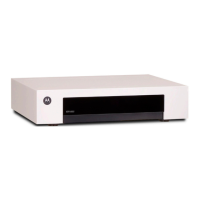
VIP1003 OVERVIEW
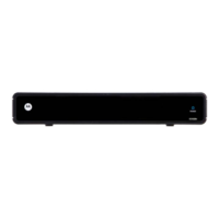
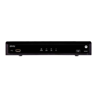
Front panel of models without display
Connecting to broadband
Connect one end of the Ethernet cable to the connector marked
ETHERNET on the rear panel of the set-top box and the other end to a hub
or the Ethernet wall connector provided by your broadband operator.
Connecting to the TV set
Connect one end of the enclosed SCART cable to the SCART connector
marked TV on the set-top box and the other end to your TV set.
Both analog audio and standard definition video are sent to the TV set
through this connection.
INSTALLING
Indicator LED:s
• Green light - the set-top box is operational.
• Flashing green light - the set-top box receives
a signal from the remote control or a keyboard.
• Red light - the set-top box is in stand-by mode.
IR receiver
Receives signals from remote control
and keyboard.
ETHERNET
for broadband
connection
SCART (TV)
for connection to TV set
(analog Standard Definition video)
SPDIF
for connection to digital
audio equipment
HDMI
for connection to TV set
(digital High Definition video)
USB
for connection
to external devices.
POWER
for connection of
external power supply
Broadband
wall outlet
or hub
TV
 Loading...