Do you have a question about the MPS M.C. Rexx QD2000 Series and is the answer not in the manual?
Explains the use of icons and signal words for better comprehension and understanding.
Details the seven FDA-identified zones in a hospital bed system where entrapment can occur.
Explains healthcare facility responsibility for matching bed components to meet entrapment guidelines.
States the intended use of M.C. Rexx low beds for resting and sleeping, not diagnosis or monitoring.
Details key physical and electrical specifications including dimensions, load capacity, and certifications.
Advises using proper sized mattresses with firm borders to prevent patient entrapment.
Introduces bed functions and emphasizes reading all instructions before operation.
Details the process for unpacking the bed, including identifying and removing shipping ties.
Explains how to secure the power cord using the Velcro strap to prevent damage or injury.
Details mattress requirements to minimize entrapment risk, including size and firm border recommendations.
Describes the installation and positioning options for the optional patient helper attachment.
Details attaching the bed extender and the need for side rail extenders with 1/2 length side-rails.
Provides step-by-step instructions and parts list for installing mattress stops on the bed frame.
Step-by-step guide for mounting roller bumper brackets and rollers to the head end of the bed frame.
Instructions for plugging in the power cord and ensuring the bed is ready for operation.
Details the installation of mounting brackets for head and foot boards using screws and nuts.
Describes securing head and foot boards, including warnings about finger entrapment.
Instructions for lifting and lowering 3/4 length siderails, with warnings about finger entrapment.
Details operating the optional pivot assist rail, including latching and rotation.
Instructions for installing and using the optional fixed assist rail on either side of the bed.
Explains how to engage and release the total lock casters for bed mobility and stability.
Details engaging and releasing directional lock hinges to prevent lateral movement of casters.
Describes engaging and disengaging the total floor lock pedal to immobilize bed ends.
Provides guidelines for safely moving the bed, including personnel requirements and checks.
Explains how to use the hand pendant controls for head, knee, and bed elevation adjustments.
Describes the function and operation of the staff controller for bed function lockout and operation.
Details the use, charging, and connection of the back-up battery for power outages.
Instructions for cleaning the bed using mild detergent, avoiding high-pressure washing or direct spray on actuators.
Specifies lubricants for pivot joints and clevis pins, advising against lithium-based grease.
Describes expected motor operation: smooth, quiet, and even movement without jerking.
Guidance on identifying and addressing abnormal noises from motors or joints.
Covers cleaning, inspection, and installation guidelines for the actuator system.
Ensures retaining rings are present on clevis pins and manually locked for safety.
Ensures all fasteners are tightened completely, but not over-tightened at pivot points.
Inspects cabling for secure placement, damage, or interference with moving parts.
Checks the power cord for damage like nicks or crushed insulation, requiring replacement with OEM parts.
Verifies casters swivel freely when unlocked and remain stationary when locked.
Ensures siderails move freely, latch securely when raised, and are not wobbly.
Inspects wood panels for damage like nicks or scratches and sealing any penetration.
Checks for loose, missing, or flaked paint and touches up as required.
Visually inspects welds, bent, or cracked components and documents concerns for service.
A chart for qualified technicians to document annual inspections and support warranty claims.
Provides guidance on recording serial numbers and contacting the service department for assistance.
Steps to diagnose and resolve issues when only some motors on the bed are not functioning.
Diagnoses issues when no bed functions work, focusing on power cord, controller, and hand pendant.
Step-by-step guide on how to initiate and process a warranty claim for parts or service.
Details the invoicing, credit, and payment procedures for validated and non-validated warranty claims.
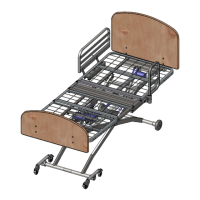
Diagram and identification of the main components of the M.C. Rexx Bed.
Explains where to find the serial number for ordering parts or contacting support.
Lists and illustrates parts for the frame and motor assembly, including actuators and controller.
Diagram and parts list for the frame and mattress deck assembly.
Illustrates and lists parts for the QD2000 series legs assembly SAR001.
Details parts related to the Hi-Lo actuator connection for the QD2000 series legs assembly.
Illustrates and lists parts for the QD2000 series legs assembly SAR002.
Illustrates and lists parts for the QD2000 series legs assembly SAR003.
Illustrates and lists parts for the QD2000 series legs assembly SAR004.
Illustrates and lists parts for the QD2250 series legs assembly SAR005.
Illustrates and lists parts for the QD2250 series legs assembly SAR006.
Illustrates and lists parts for the QD2250 series legs assembly SAR008.
Illustrates and lists parts for the QD2250 series legs assembly SAR007.
Illustrates and lists the components of the total floor lock assembly.
Illustrates and lists parts for the wheel assembly at the head end.
Illustrates and lists parts for the caster arm assembly, including torque specifications.
Illustrates and lists parts for the right-hand caster arm with a total floor lock.
Illustrates and lists parts for the left-hand caster arm with a total floor lock.
Illustrates and lists parts for the left-hand caster arm with a directional lock.
Illustrates and lists parts for the left-hand caster arm assembly with a directional lock.
Illustrates and lists the components for the bed extender head or foot end assembly.
Lists the parts for the hand pendant control, including the pendant and extension cable.
Illustrates and lists parts for the fixed assist rail, available for left and right sides.
Illustrates and lists parts for the three position assist rail, including mounting and rail components.
Illustrates and lists parts for the left-side 3/4 length collapsible side rail assembly.
Illustrates and lists parts for the right-side 3/4 length collapsible side rail assembly.
Illustrates and lists parts for the left-side 1/2 length side rail assembly.
Illustrates and lists parts for the right-side 1/2 length side rail assembly.
Illustrates and lists parts for the pendant rail mount assembly.
Illustrates and lists parts for mounting the pendant holder to the head or foot board.
Illustrates and lists parts for the 3-switch lockout box, including the box and cable.
Illustrates and lists parts for the gooseneck pendant holder mounted to a head/foot board.
Illustrates and lists parts for the gooseneck pendant holder mounted to an assist rail.
Illustrates and lists parts for the foot end staff controller, including the board and box.
| Brand | MPS |
|---|---|
| Model | M.C. Rexx QD2000 Series |
| Category | Medical Equipment |
| Language | English |