MARINE RADIO CO.,LTD.
주/선박무선
Subject : Auto Exchanger Page : (42 / 46)
Date : 2010.10.13 Doc. : MCX-5000S_ENG_R1
(QAS-ADD-008/1/10.10.13) manual\pabx\mcx-5000S\MCX-5000S_eng.doc
(
MARINE RADIO CO., LTD.)
MRC
The following figure shows the signal flow:
2.6 Power Supply Circuit
The power supply circuit includes AD and DA noise filter, AC voltage transformer, rectification
circuit and smoothing circuit. Also, it includes the power switch. The DC-28 V power is supplied to
switching regulator unit, changed to DC-24V in regulator, and transmitted to switching regulator and
ring generator. The switching regulator creates DC-2V, 5V, 8V and 12V supplied to each circuit
and they are transmitted to rectification circuit. The I/O of switching regulator is insulated
to DC power. The ring generator creates the power required for ring and transmits it. If the main
power is in power failure, it operates the AC/DC switch and supply the power to DC power. If the
failure is generated in switching circuit or CPU notifies the abnormal subscribers telephone state,
the power supply circuit operates the relay and generates the alarm.
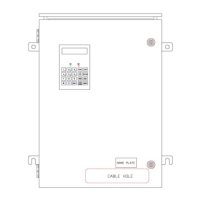
The following figure shows the configuration diagram of this device: