switch that
Page 5
(82A044) TDMv1017
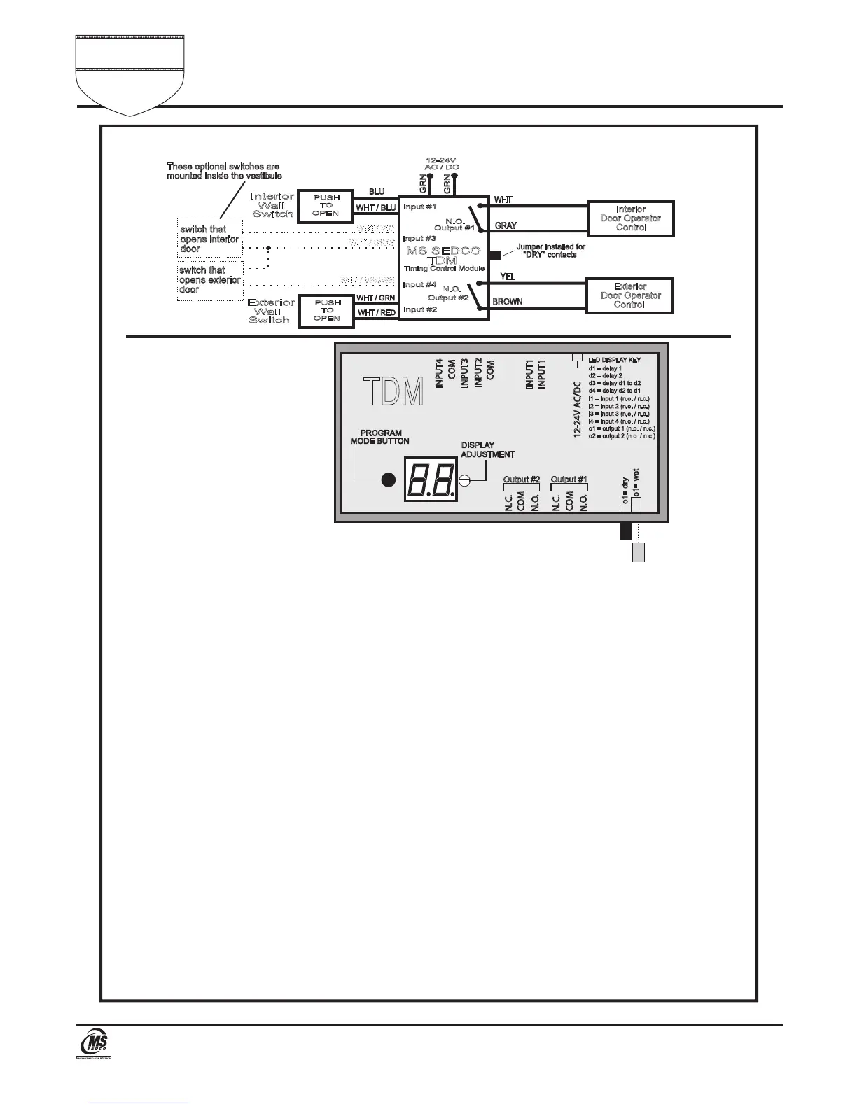
FIGURE 4—Vestibule Sequencing
Once the TDM has been wired for the above application, programming of the device is as follows:
1) Apply power to the unit. The display will flash double bars (––) indicating that the unit is in its normal
operating ready mode.
2) To begin programming, depress the PROGRAM MODE BUTTON one time. The first parameter to be
programmed will appear on the display. This is the delay time, or "on time" of the output #1 and is
displayed as d1 followed by the time setting of 2.0 (Factory Setting) which indicates 2.0 seconds (It
will flash between the two). This is the time duration that you want the interior door to remain open
(It's usually set around 4-5 seconds). To adjust the time setting, use a small screwdriver and rotate
the DISPLAY ADJUSTMENT clockwise to increase and counterclockwise to decrease the time setting.
After the desired value is displayed, depress the PROGRAM MODE BUTTON again to save the value.
The display will now read d2. d2 is the delay time or "on time" of output #2. This is the time setting
that you want for the exterior door to remain open. This is usually set around 4-5 seconds. To adjust
the setting, rotate the DISPLAY ADJUSTMENT until the desired value is displayed and then depress
the PROGRAM MODE BUTTON. The display should then read d3. This is the setting for the delay
time between the activation of the interior door and the exterior door. This time is usually set around
1-4 seconds. Again, adjust the setting and then depress the PROGRAM MODE BUTTON. The display
should now read d4. This is the delay time between the opening of the doors going in the opposite
direction. Adjust this value in the same manner as before. When the PROGRAM MODE BUTTON is
depressed, i1 will then be displayed. Now wait 30 seconds until the double bars (––) appear,
indicating that the unit is in its normal operating ready mode.
3) You are now ready to test your installation. If any of the time settings need to be changed, make the
change and press the PROGRAM MODE BUTTON once to save the new value. Then wait 30 seconds
until the double bars (––) appear again, indicating that the unit is in its normal operating mode.
4) During operation of the unit, the display will indicate its operating status. Please refer to Figure 5 at
the end of this installation manual.
PROGRAMMING
PROCEDURE
MS SEDCO
TDM
Timing Control Module
12-24V
AC / DC
Interior
Door Operator
Control
Exterior
Door Operator
Control
N.O.
N.O.
Output #1
Output #2
GRAY
WHT
BROWN
YEL
GRN
GRN
Wall
Interior
Switch
PUSH
TO
OPEN
BLU
WHT / BLU
Wall
Exterior
Switch
PUSH
TO
OPEN
WHT / GRN
WHT / RED
WHT / VIO
WHT / GRAY
WHT / BROWN
switch that
opens interior
door
opens exterior
door
These optional switches are
mounted inside the vestibule
Jumper installed for
"DRY" contacts
input #1
input #2
input #4
input #3
TDM
INPUT 4
INPUT 3
INPUT 2
INPUT 1
12-24V AC/DC
INPUT 1
COM
COM
COM
COM
N. O.
N. C.
N. C.
N. O.
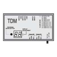
PROGRAM
MODE BUTTON
DISPLAY
ADJUSTMENT
LED DISPLAY KEY
d1 = delay 1
d2 = delay 2
d3 = delay d1 to d2
d4 = delay d2 to d1
i1 = input 1 (n.o. / n.c.)
i3 = input 3 (n.o. / n.c.)
i2 = input 2 (n.o. / n.c.)
i4 = input 4 (n.o. / n.c.)
o2 = output 2 (n.o. / n.c.)
o1 = output 1 (n.o. / n.c.)
o1= dry
o1= wet
Output #1
Output #2
Universal Time Delay Module INSTALLATION INSTRUCTIONS
The
Series
TDM
Commander
™
7898 Zionsville Road Indianapolis, Indiana 46268
Telephone: (317) 842-2545 www.mssedco.com custsvc@mssedco.com


 To Next Page
 Loading...