MSAChanging Components
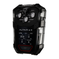
ALTAIR 4
16
GB
(2) Remove the four case screws, and remove the case front while carefully not-
ing the orientation of the sensor gasket.
(3) Gently lift out and properly discard the sensor to be replaced.
Z Using fingers only, gently remove the toxic, combustible, and oxygen sen-
sor by gently rocking it while pulling it straight from its socket.
(4) Remove the screws from the sensor display bracket (shown in figure 4).
(5) Un-solder the two charge pins (shown in figure 5) that connect the PCB with
the back case.
(6) Gently remove the PCB and battery assembly from the back case.
(7) Install new PCB and battery assembly with the old back base.
(8) Solder the two charge pins of the new PCB and battery assembly to the back
case.
(9) Re-install the sensor/display plastic holder and screws.
(10) Re-install the sensors and sensor gasket in the front case.
(11) Re-install the case screws.
(12) If the instrument had special settings, go into the setup menu and re-enter the
specialized settings.
(13) Calibrate the instrument after the sensors have been stabilised.
Danger!
Verification of calibration response is required; otherwise, the instrument
may not perform as designed resulting in death or serious injury.
It is the user's responsibility to follow all applicable regulations and to
ensure continued compliance with the certification as marked on the la-
bel.

 Loading...