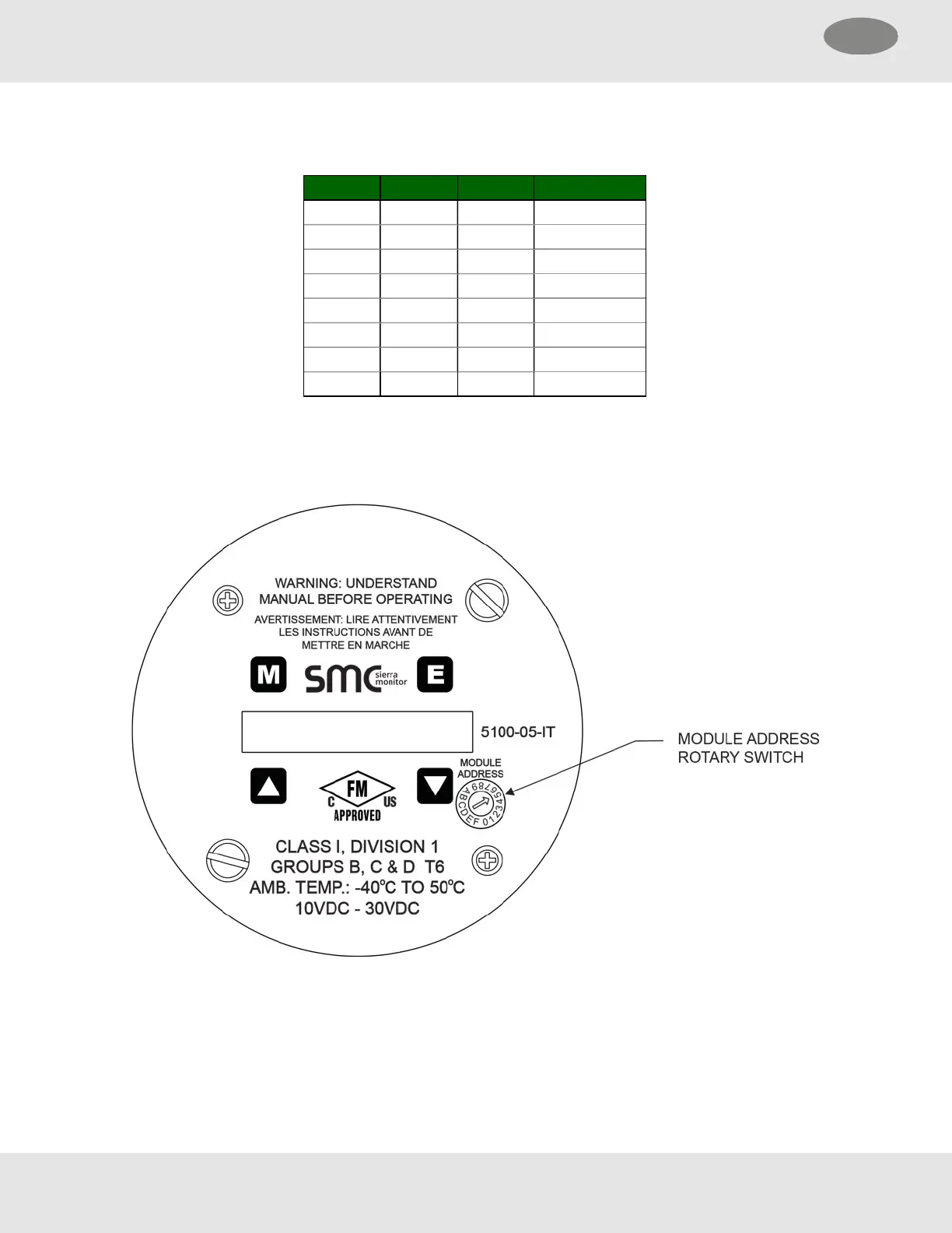
4.5 Module Address Switch
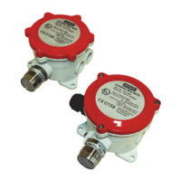
For digital interface applications the module address switch (or Modbus node) must be set per the table below.
Position Address Position Address
1 Sensor 1 9 Sensor 09
2 Sensor 2 A Sensor 10
3 Sensor 3 B Sensor 11
4 Sensor 4 C Sensor 12
5 Sensor 5 D Sensor 13
6 Sensor 6 E Sensor 14
7 Sensor 7 F Sensor 15
8 Sensor 8 0 Software Menu
NOTE:Use selector switch to pick Sentry PSG addresses 1 through 8 only. If using Modbus output sensor
addresses 1-15 are available. Position 0 allows the Modbus Address to be set by software menu, in the range
16-254.
18 SMC 5100-XX-IT Toxic Gas Detector Module
4 Installation US

 Loading...