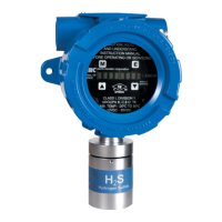
1.2 Product Configuration
Various module mounting configurations can be implemented without special fixtures. Where applicable, these options are
factory configured prior to shipment. Mounting configuration can be selected by the installer or field technician and are fully
described in this manual. Sensor must always be oriented downward.
1.3 Theory of Operation
Electrochemical sensors are fuel cell-like devices consisting of an anode, cathode, and electrolyte. The components of the
cell are selected so a subject gas, allowed to diffuse into the cell, will cause a chemical reaction and generate a current. The
cells are diffusion limited so the rate the gas enters the cell is solely dependent on the gas concentration. The current
generated is proportional to the rate of consumption of the subject gas in the cell.
Sierra Monitor electrochemical sensors provide improved reliability by allowing the gas to diffuse into the sensor through a
capillary port, rather than diffusing through membranes. The result is an extremely stable sensor with very low temperature
and pressure coefficients and the capability to monitor gas as ppm.
1.4 Modes of Operation
1.4.1 Classic Sentry Interface
IT gas sensor modules can be installed on Sierra Monitor Sentry Model 5000 controllers Ver. 6.XX MFD after 9/1/95. When
it is installed in a Sentry system the IT module must have a unique address which can be established by setting an address
between 1 and 8 on the Module Address Switch accessible from the cover plate as illustrated in Section 4.5 Module Address
Switch. Section 4.5 Module Address Switch also provides the wiring terminations for connections to the Sentry controller.
NOTE:The Model # 5100-88-IT CO2 gas sensor module range is 0-5000 ppm. Therefore, the Sentry Controller
must be configured for a 0-100 % full scale input. The Sentry cannot display engineering units up to 5000. The
alarm set points need to be set as a percentage of full scale. For example, a 2500 ppm alarm set point is equal
to 50% scale.
When the module is operated in conjunction with a Sentry controller, the alarm relay set-up (Section 5.3 Main Menu) should
be set to “Sentry”, allowing the Sentry controller to manage alarm relay action rather than the 5100-XX-IT Gas Sensor
Module.
1.4.2 Modbus Operation
An RS-485 Modbus RTU serial interface allows direct connection to standard PLCs and DCSs. The Module Address Switch
(Section 4.5 Module Address Switch) allows the user to select up to 15 different Modbus addresses.Also, an additional 254
Modbus addresses are available via menu selection. Section 4.5 Module Address Switch provides the wiring terminations
for Modbus connections. The 5100-XX-IT provides the wiring terminations for Modbus connections.
1.4.3 Analog Operation
The analog 4-20 mA interface allows direct connection to standard controller and distributed system. The module is an
active current source.
The standard configuration is set up for a 3-wire non-isolated connection. An optional 4-wire isolated connection is also
available and can be enabled by changing JP1 and JP2. (Section 4.5 Module Address Switch)
1.4.4 Remote Sensor
The Remote Sensor option can be used to remotely mount some sensors up to 15’ from the transmitter. Refer to Section 11
Remote Sensor Drawing for allowable distances.
SMC 5100-XX-IT Toxic Gas Detector Module 7
US 1 Product Description

 Loading...