wet or damp, it is good practice to loop or bend the entry into
the unit that prevents water incursion.
For Milliamp Output
The Ultima X Series Gas Monitors may be connected to any
device capable of accepting 4 to 20 mA analog signals such as:
• Model 5000 unit (with 4 to 20 mA inputs)
• Quad Gas Controller
• Programmable controllers
• DCS’s, etc.
An external power supply is required. (For power requirements,
see Chapter 3, "Specifications".) All connections should be made
by following appropriate wire code procedures.
• See TABLES 1-1 through 1-4 for typical cable length and wire
size for installation.
"
WARNING
When using any of the the Ultima X Series accessories (such as
relays) with the 4 to 20 mA output Ultima X Series Gas Monitor,
a three-wire connection must be used. Failure to use a three-wire
connection could damage the electronics within the Ultima X Series
Gas Monitor which can result in serious personal injury or death.
Be sure to install your Ultima X Series Gas Monitor according to National
Electrical and local procedural codes. Failure to do so can result in
an unsafe condition.
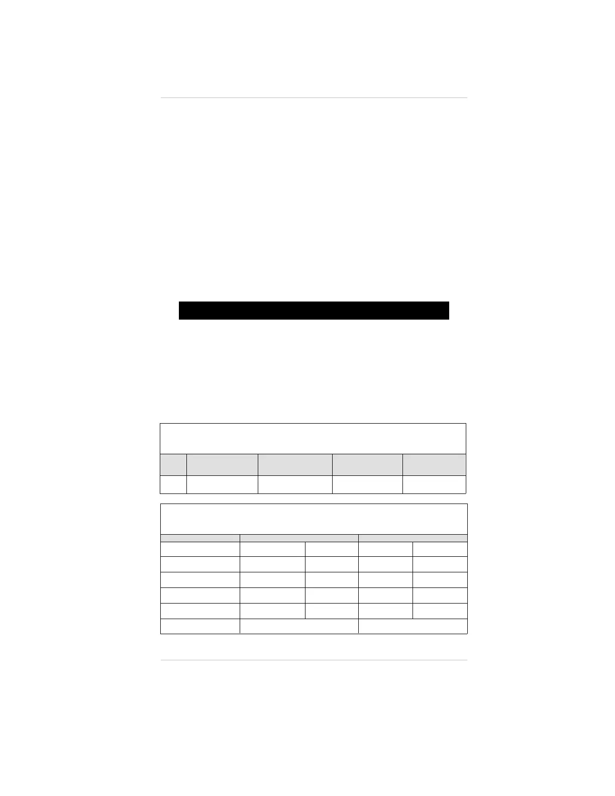
Table 1-1. Power Signal Cable Length and Wire Size (Toxic Gas
or Oxygen) Sensor, 4-20 mA Signal Output (Two Wire Sensor)
WIRE
SIZE
MAXIMUM CABLE
LENGTH IN FEET
AT 24 VDC
MAXIMUM LOAD
RESISTANCE
MAXIMUM CABLE
LENGTH IN FEET
AT 12 VDC
MAXIMUM
LOAD
RESISTANCE
22
AWG
7,000 600 Ohms 4,000 100 Ohms
Table 1-2. Ultima XE and XA Maximum Cable Length and
4-20 mA Signal Load
POWER SUPPLY 24 VOLTS 12 VOLTS
CONFIGURATION NO RELAYS
RELAYS
INSTALLED
NO RELAYS
RELAYS
INSTALLED
22 AWG CABLE
1000 FEET 800 FEET
- - - - - -
18 AWG CABLE
2500 FEET 2100 FEET 900 FEET 640 FEET
16 AWG CABLE
4200 FEET 3000 FEET 1400 FEET 900 FEET
12 AWG CABLE
10,000 FEET 7700 FEET 3600 FEET 2200 FEET
MAXIMUM LOAD ON
4 - 20 mA SIGNAL
600 OHMS 300 OHMS
Chapter 1, Installation
1-7

 Loading...


