NOTE: TABLES 1-1 through 1-4 do not apply to Ultima X
Series Gas Monitors with Internal Relays. If Internal
Relays exist, see Appendix A.
Typical Ultima X Series Gas Monitor Wiring
• Two-wire 4 to 20 mA Ultima X Series Monitors operate in the
current loop mode (FIGURE 1-10 for general-purpose)
(FIGURE 1-12 for explosion-proof)
• Three-wire Ultima X Series Monitors operate in the current
source mode (see FIGURE 1-11 for general-purpose)
(FIGURE 1-13 for explosion-proof).
1. Identify the main pc board as a two-wire or a three-wire unit:
• For XA Gas Monitors
while looking at the main pc board, locate the identifying
label on the underside of the lid:
• A-ULTX-PCB-A-B is a two-wire unit
• A-ULTX-PCB-A-E is a three-wire unit
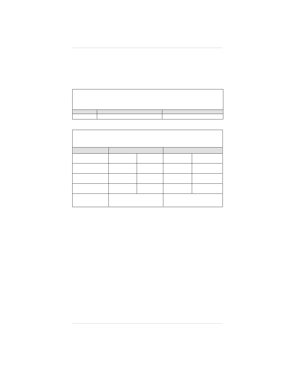
Table 1-3.
Cable Length and Wire Size (Power Supply 24 VDC) (Toxic Gas
or Oxygen) Sensor, 4-20 mA Signal Output (Three Wire Sensor)
WIRE SIZE MAXIMUM CABLE LENGTH IN FEET MAXIMUM LOAD RESISTANCE
22 AWG 12,000 600 Ohms
Table 1-4. Ultima XIR Maximum Cable Length
and 4-20 mA Signal Load
POWER SUPPLY 24 VOLTS 12 VOLTS
CONFIGURATION NO RELAYS
RELAYS
INSTALLED
NO RELAYS
RELAYS
INSTALLED
18 AWG CABLE
2000 FEET 1500 FEET 300 FEET 250 FEET
16 AWG CABLE
3500 FEET 2500 FEET 500 FEET 400 FEET
12 AWG CABLE
5000 FEET 4000 FEET 900 FEET 600 FEET
MAXIMUM LOAD
ON 4 - 20 mA
SIGNAL
600 OHMS 300 OHMS
Chapter 1, Installation
1-8

 Loading...


