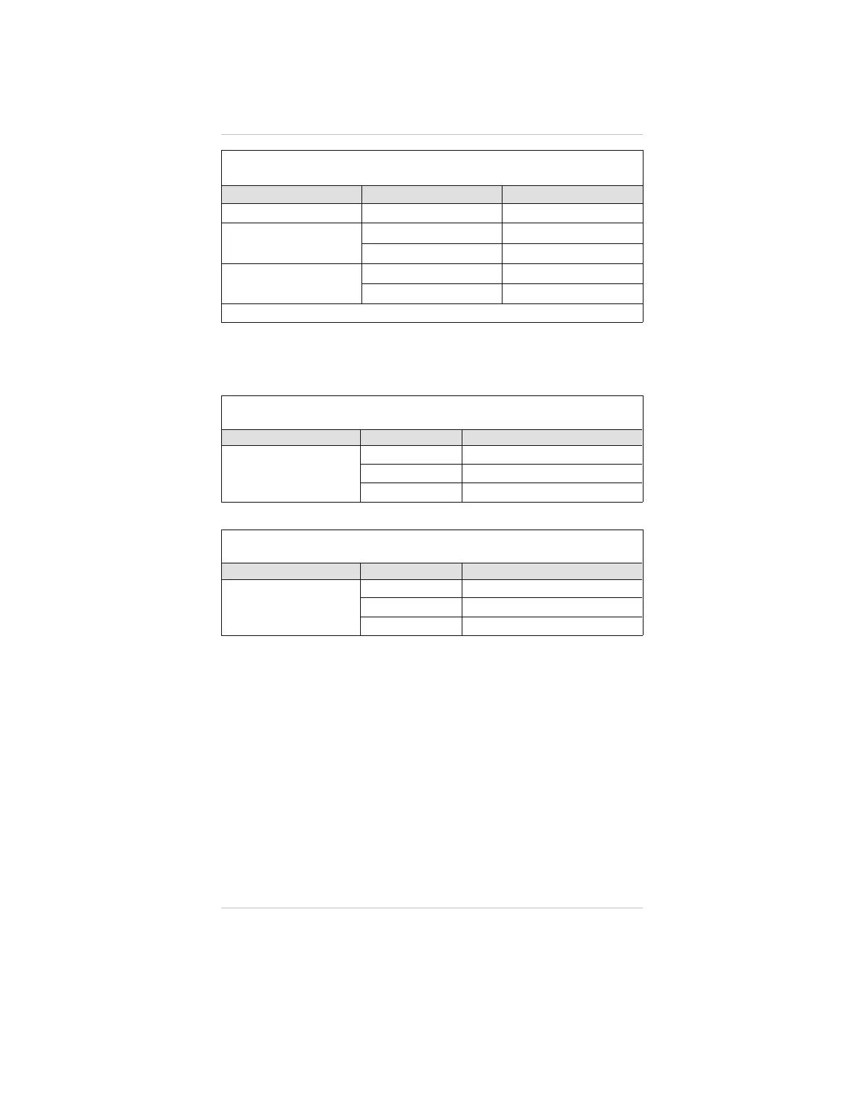
Table 1-5. Remote Module Wiring and Placement*
GAS TYPE MINIMUM WIRE SIZE MAXIMUM DISTANCE
Toxic and Oxygen
20 AWG 100 FEET
Catalytic Combustible
18 AWG 50 FEET
16 AWG 100 FEET
IR Combustible
16 AWG 50 FEET
12 AWG 100 FEET
* CE-Approved instruments have a maximum 50-foot distance.
TABLE 1-6 shows suggested cables for Ultima X Series
inhalations; other cables are available which are also adequate.
Table 1-6. Remote Sensor Wiring Cable
SUPPLIER CATALOG NUMBER DESCRIPTION
ALPHA WIRE CORP.
5525
5 cond., shielded, 18 AWG
5535
5 cond., shielded, 16 AWG
5514
4 cond., shielded, 20 AWG
Table 1-7. Low Temperature Wiring Cable
SUPPLIER CATALOG NUMBER DESCRIPTION
ALPHA WIRE CORP.
45525
5 cond., shielded, 18 AWG
45366
6 cond., shielded, 16 AWG
45545
5 cond., shielded, 14 AWG
At the Ultima X Series Remote Sensor Location:
1. Open the Ultima X Series Remote Sensor cover by
removing lid.
2. For the Ultima XA Gas Monitor, route the cable from the
Gas Monitor through a customer-supplied opening in the
enclosure and wire it to the terminal block (FIGURE 1-4).
For the Ultima XE or XIR Gas Monitor, route the cable from
the Gas Monitor through a wire entry hole in the enclosure
and wire it to the terminal block (FIGURE 1-5 or 1-6).
3. Verify the identity of each conductor of the cable and
connect the wire to the terminal block.
4. Re-install the cover of the Ultima X Series Remote Sensor
Chapter 1, Installation
1-13

 Loading...


