Step 5.
Connect both powerbases with the supplied 3.5mm mini jack cable
by plugging it into the 12 volt remote trigger connections. Be sure to
check that the primary powerbase ‘power control switch’ is set to the
‘NORMAL’ position. The secondary powerbase switch set to ‘LINKED’.
This allows the primary powerbase to control the secondary one
without them having to be turned on/o seperatley.
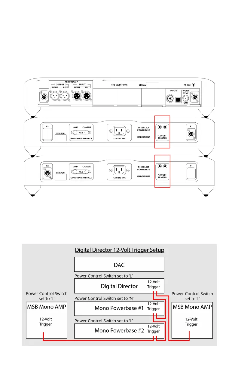
12 Trigger Setup Diagram
The diagram below represents how you would connect the full lineup
of MSB products. If you do not have a portion of the product line
represented below, disregard that portion of the connections and the
system will function the same.