2 INSTALLATION INSTRUCTIONS
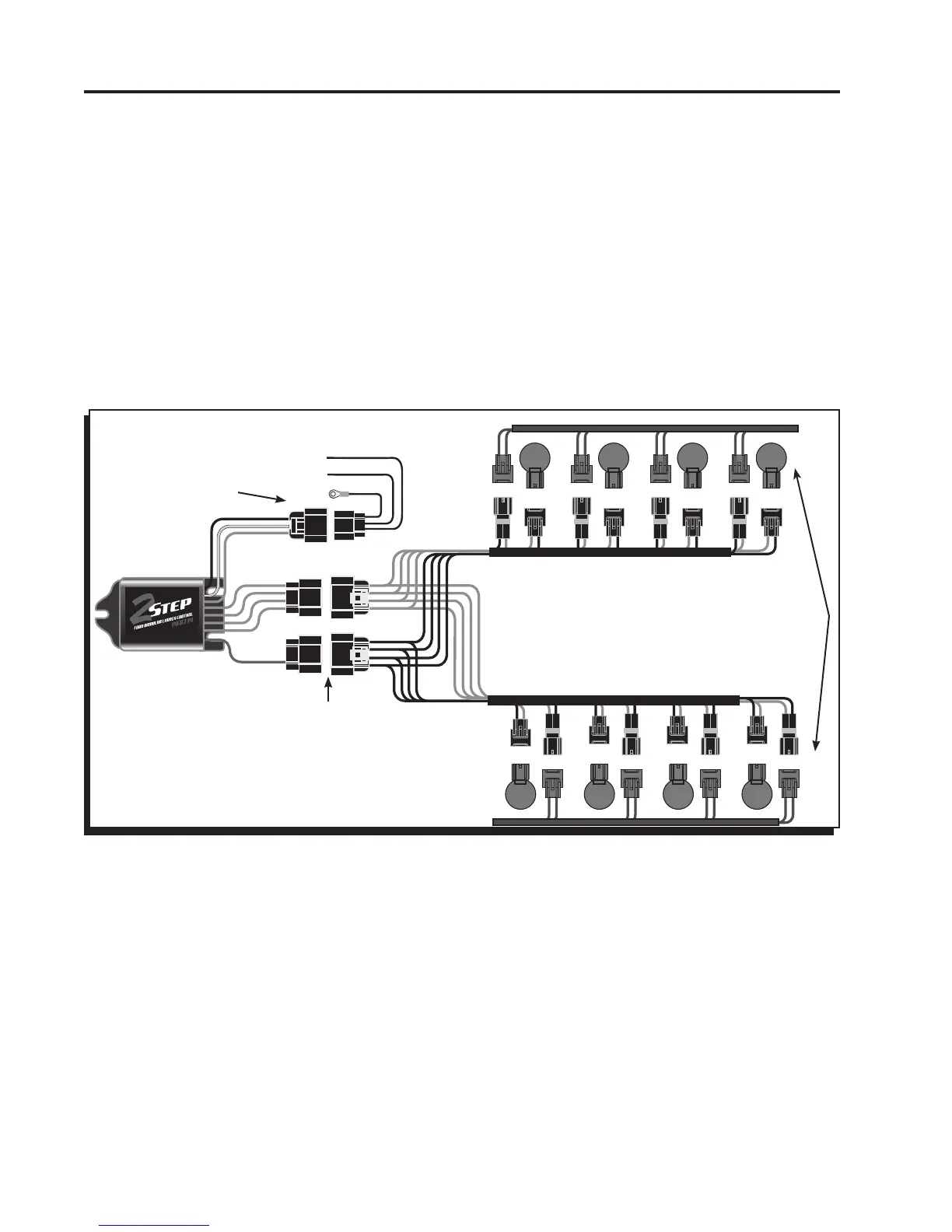
Figure 1 Wiring the 2-Step Launch Control.
1. Connect the 3-pin harness to the 2-step and connect the Black wire to the good engine or chassis
ground.
2. Disconnect the 2-pin connectors from each of the eight ignition coils.
3. Connect all eight of the 2-pin male connectors from the MSD harness into the factory coil connec-
tors.
kcalB htiw rotcennoc eht ot petS-2 eht morf eriw deR elgnis eht htiw rotcennoc nip-8 eht gulP.4
wires.
5. Turn the key to the On position – do NOT start the engine. Look at the LED on the 2-Step:
LED On – This confirms that the wiring is correct and you can move to step 6 (Figure 1).
LED Off – The wiring is different for this application and needs to be changed. Turn the key Off,
plug the 8-pin connector with the eight Gray wires into the connector with the single
Red wire (Figure 2).
6. Connect the 8-pin harness with the tan wires to the remaining connector on the harness.
7. Connect all eight of the female 2-pin connectors from the MSD harness into the factory coils.
GROUND
ACTIVATION
WIRES
WHITE BLUE
BLUE
ACTIVATES
WITH 12 VOLTS
OR GROUND
TAN
RED
GRAY
BLACK
STEP 4
STEP 3
STEP 2
 Loading...