GE70 (MS-1756) Disassembly Guide
4、THERMAL-KIT、CPU 、DRAM AND WIRELESS
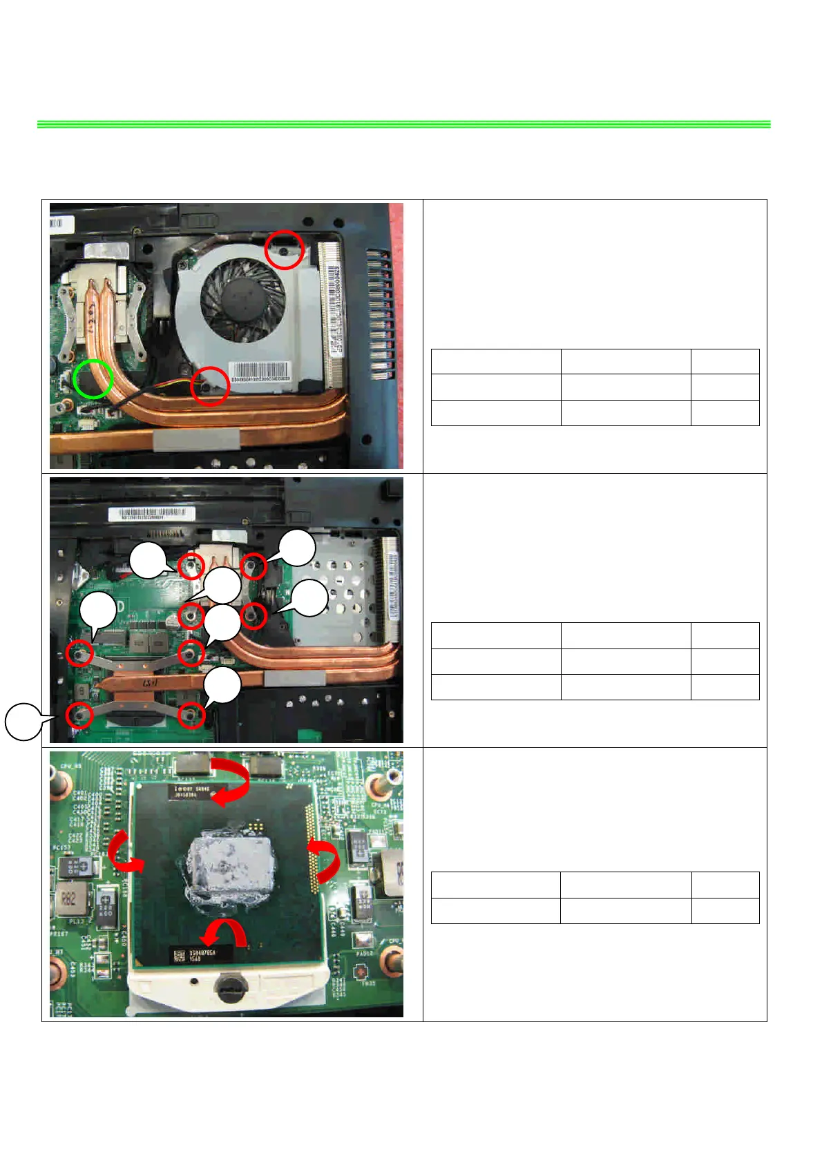
4.1: Remove the 2 screw(M2.5*5.5mm) and FAN
cable, after that remove the Fan.
Attention:the screw driver torque is 2.0-2.5Kgf-cm
Component P/N Qty
Screw E43-1255501-H29 1
FAN E33-0800410-MC2 1
4.2: Remove the 8 screws (M2.5*4.5mm), after
that remove the Heatsink.
Attention:the screw driver torque is 2.0-2.5Kgf-cm
Component P/N Qty
Screw E43-1254502-G68 6
Heatsink E31-0403231-TA9 1
4.3:Open the CPU Slot with Screw Driver, then
remove CPU Module as below.
Component P/N Qty
CPU A13-2320186-I06 1

 Loading...