13
Overview of Components Overview of Components
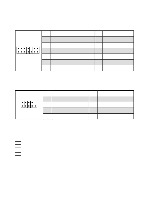
JTPM1: TPM Module Connector
This connector is for TPM (Trusted Platform Module). Please refer to the TPM
security platform manual for more details and usages.
1
2 14
13
1 LPC Clock 2 3V Standby power
3 LPC Reset 4 3.3V Power
5 LPC address & data pin0 6 Serial IRQ
7 LPC address & data pin1 8 5V Power
9 LPC address & data pin2 10 No Pin
11 LPC address & data pin3 12 Ground
13 LPC Frame 14 Ground
JCOM1: Serial Port Connector
This connector allows you to connect the optional serial port with bracket.
1
2 10
9
1 DCD 2 SIN
3 SOUT 4 DTR
5 Ground 6 DSR
7 RTS 8 CTS
9 RI 10 No Pin
EZ Debug LED
These LEDs indicate the status of the motherboard.
CPU - indicates CPU is not detected or fail.
DRAM - indicates DRAM is not detected or fail.
VGA - indicates GPU is not detected or fail.
BOOT - indicates booting device is not detected or fail.
 Loading...