2-20
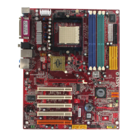
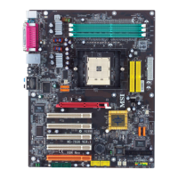
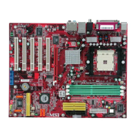
MS-6702 ATX Mainboard
Front Panel Connectors: JFP1 & JFP2
The mainboard provides two front panel connectors for electrical con-
nection to the front panel switches and LEDs. JFP1 and JFP2 are compliant
with Intel
®
Front Panel I/O Connectivity Design Guide.
CD-In Connector: J4
The connector is for CD-ROM audio connector.
J4
GND
R
L
Power
LED
Speaker
1
2
7
8
JFP2
1
2
9
10
JFP1
HDD
LED
Reset
Switch
Power
LED
Power
Switch
PIN SIGNAL DESCRIPTION
1 HD_LED_P Hard disk LED pull-up
2 FP PWR/SLP MSG LED pull-up
3 HD_LED_N Hard disk active LED
4 FP PWR/SLP MSG LED pull-up
5 RST_SW_N Reset Switch low reference pull-down to GND
6 PWR_SW_P Power Switch high reference pull-up
7 RST_SW_P Reset Switch high reference pull-up
8 PWR_SW_N Power Switch low reference pull-down to GND
9 RSVD_DNU Reserved. Do not use.
JFP1 Pin Definition
PIN SIGNAL PIN SIGNAL
1 GND 2 SPK-
3 SLED 4 BUZ+
5 PLED 6 BUZ-
7 NC 8 SPK+
JFP2 Pin Definition
MSI Reminds You...
If the Power LED on the front panel flashes every two seconds,
this signal tells you that one of the power connection has been
protected; if the Power LED flashes every one second, it tells that
the CUP has been protected due to overheating. To refresh the
system, please disconnect the power cable from the computer,
and then reconnect the power cable to the computer again in at
least five senconds.
 Loading...