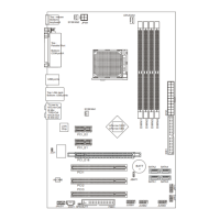
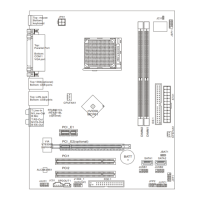
2. Insert the memory module vertically into the DIMM slot. Then push it in until the golden finger
on the memory module is deeply inserted in the DIMM slot.
3. The plastic clip at each side of the DIMM slot will automatically close.
Power Supply
The mainboard supports ATX power supply for the power system. Before inserting the power
supply connector, always make sure that all components are installed properly to ensure that no
damage will be caused. A 350W or above power supply is suggested.
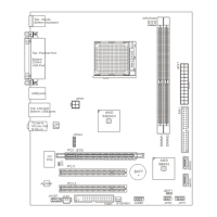
ATX 24-Pin Power Connector: JWR2
This connector allows you to connect an ATX 24-pin power supply. To
connect the ATX 24-pin power supply, make sure the plug of the power
supply is inserted in the proper orientation and the pins are aligned. Then
push down the power supply firmly into the connector.
You may use the 20-pin ATX power supply as you like. If you’d like to use
the 20-pin ATX power supply, please plug your power supply along with
pin 1 & pin 13. There is also a foolproof design on pin 11, 12, 23 & 24 to
avoid wrong installation.
ATX 12V Power Connector: JPW1
This 12V power connector is used to provide power to the CPU.
Floppy Disk Drive Connector: FDD1
The mainboard provides a standard floppy disk drive connector
that supports 360K, 720K, 1.2M, 1.44M and 2.88M floppy disk
types.
IDE Connector: IDE1
The mainboard has a Ultra DMA 66/100/133 controller that provides PIO mode 0~4, Bus Master,
and Ultra DMA 66/100/133 function. You can connect up to 2 hard disk drives, CD-ROM, 120MB
Floppy and other devices.
The IDE1 can connect a Master and a Slave drive. You must
configure second hard drive to Slave mode by setting the
jumper accordingly.
 Loading...