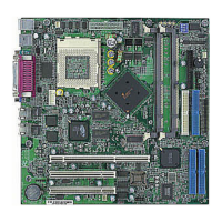
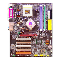
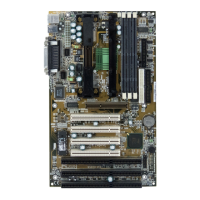
MS-6119 ATX BX2 Mainboard
MICRO-STAR INTERNATIONAL COMPANY LTD.
Specification & User’s Guide
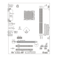
JMODE1
+12V +5V
(default)
11
3
3
+12V
PWD
VCC
+12V
PWD
VCC
Note: a. Short 1-2 pin, if you’re using Intel
®
or MXIC flash memory and you want to flash the ROM data.
b. Short 2-3 pin, if you’re using Intel
®
or MXIC flash memory for normal operation.
c. Leave JMODE1 open, if you’re using Winbond flash memory.
External Battery Connector: JBAT1
A battery must be used to retain the mainboard configuration in CMOS RAM. If you use the on-board
battery, you must short 1-2 pins of JBAT1 to keep the CMOS data.
Keep Data
Clear Data
1
1
3
3
JBAT1
Note: You can clear CMOS by shorting 2-3 pin, while the system is off. Then, return to 1-2 pin position.
Avoid clearing the CMOS while the system is on; it will damage the mainboard.
Jumpers
Flash ROM Programming Voltage: JMODE1
This jumper is for setting the voltage of the Flash ROM BIOS.
 Loading...