P E R F E C T S O L U T I O N S I N G A S A L A R M S Y S T E M S
www.m s r - e l e c t r o n i c . d e
PolyG ar d ® 2 M SC 2 – Data Sh eet a n d U s er M anu a l
MSR-Electronic GmbH ::: Würdinger Str. 27 + 27A ::: 94060 Pocking
::: Germany
Specifications subject to change without notice
PolyGard® is a registered trademark of MSR-Electronic GmbH
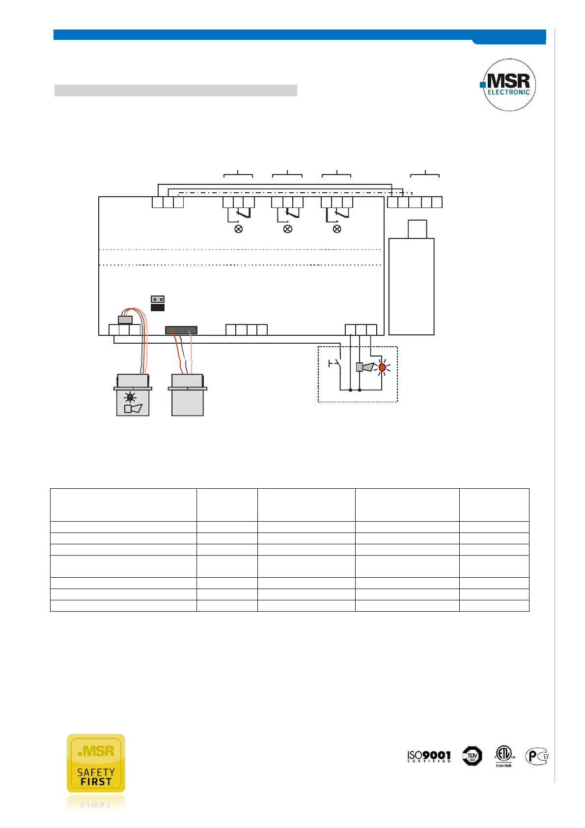
ELECTRICAL CONNECTION 90-240 V AC / 24 V DC 15 VA (qualified technicians only)
FUNCTION OUTPUTS
Reaction
Relay 1
(Alarm 1)
Reaction
Relay 2, horn &
flashlight (Alarm 2)
Reaction
Relay 3
(collective fault message)
Gas signal < alarm threshold 1
Gas signal ≥ alarm threshold 1
Gas signal ≥ alarm threshold 2
Gas signal < (alarm threshold 2 -
Hysterese) aber ≥ alarm threshold 1
No fault, but maintenance due
Note Relay 1 & 2:
Status OFF means: “Alarm off“ = Relay coil energized
Status ON means: “Alarm on“ = Relay coil de-energized
Note Relay 3:
Status OFF means: “No fault and MSC2 in normal operation“ = Relay coil energized
Status ON means: “ Fault ON or MSC2 without tension“ = Relay coil de-energized
Note 1: Status OFF = Relay is configured “Alarm ON = Relay“ or the MSC is free from tension.
Note 2: Alarm thresholds can have the same value, therefore the relays and/or the horn and flashlight can be triggered
together.
0.5/ 1.0 Vol %
1.0/ 1.8 Vol%
Alarm Threshold
Selectable via Jumper
Power
Supply
230 V AC
(1 Vol %)
Relay
Alarm 1
(1.8 Vol %)
Relay
Alarm 2
Relay
Fault
X1 X2 X3 X4
1 112 223 3
1 1 1 PE N L2 2 2 2 V-3 3 3 3 V+
+24 V
GND
Multi Sensor Controller MSC2 -Carrier-
CO2
Sensor
Field Bus Digital
Output
SC2-I1164-B
GND
DI_1
Power Unit
90 to 240 V AC
24 V DC, 15 VA
DI_2
GND
Horn
X12
1
X13
BUS_A
BUS_B
X11
Digital
Input
Acknow.
Horn
(1.8 Vol %)
Alarm 2
(0 - 5 Vol %)
3 4
AO_01
GND
Flashlight
(Option)
* Connect to ground, if at 230 V supply, a potential
difference to tground (floating ground) isn’t allowed.