MOUNTAIN SAFETY RESEARCH
®
MOUNTAIN SAFETY RESEARCH®
4000 First Avenue South
Seattle, WA 98134 U.S.A.
800-531-9531 | 206-505-9500
www.msrgear.com
3
7
6
5
8
4
2
12
14 15 16
17
18
19
20
21
22
A
B
C
D
E
F
G
H
I
J
L
M
K
A
B
C
D
E
F
H
I
J
K
j
a
b
c
d
i
g
f
h
e
k
a
b
c
d
n
m
f
h
g
j
k
A B
l
l
PN# 33-344
G
(WLU only)
(WLU only)
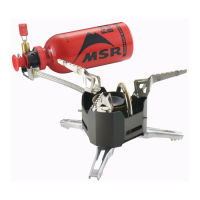
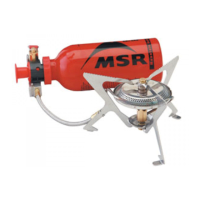
A
Burner Head
B
Mixer Tube
C
Pot Support Legs
D
Generator Tube
E
Jets
F
Shaker Needle
G
Priming Wick
H
Priming Cup
I
Fuel Line Cable
J
Catch Arm
K
Fuel Line
L
Liquid Fuel Adaptor
M
Canister Fuel Adaptor
INCLUDED IN THIS KIT:
1.
Jet & Cable Tool
2.
O-Rings. See Sizing Chart
3.
Priming Wick
4.
Pump Cup Oil
5.
Safety Pin
6.
Pump Seal
7.
Air Tube
8.
Fuel Tube Bushing
9.
Check Valve Plug
10.
Pump Cup
11.
Shaker Needle (with cover)
12.
Check Valve Ball
13.
Check Valve Spring
14.
WhisperLite G Jet (No mark)
15.
WhisperLite Internationale G Jet (IG)
16.
WhisperLite Internationale K Jet (K)
17.
Jet Cleaning Wire
18.
Check Valve Assembly
19.
Fuel Tube and Filter
20.
WhisperLite International/Universal UG Jet
21.
WhisperLite International/Universal UK Jet
22.
WhisperLite Universal UC Jet
a.
Fuel Tube Bushing
b.
Fuel Tube O-ring
c.
Control Valve Stop Nut
d.
Control Valve (O-Ring)
e.
Pump Seal
f.
Plunger
g.
Plunger Bushing
h.
Pump Cup
i.
Locking Holes
j.
Check Valve
k.
Dip Tube
l.
Fuel Filter
m.
Air Tube
n.
Fuel Bottle O-ring
STOVE MAINTENANCE
Deposits in the Jet and Fuel Line reduce fuel flow and impair stove perfor-
mance. Minor deposits in the Jet can usually be cleared with the Shaker
Needle (F). More extensive deposits may require extensive cleaning of the Jet
or Fuel Line.
QUICKLY CLEARING THE JET
1. Close the Control Valve firmly and allow stove to cool.
2. Shake the stove up and down. An audible “rattle” is proof that the
Shaker Needle is functioning as designed.
3. Restart the stove. If performance does not improve,
See EXTENSIVE CLEANING OF THE JET AND FUEL LINE.
EXTENSIVE CLEANING OF THE JET AND FUEL LINE
1. Unscrew the Priming Cup (H). Remove the Priming Wick (G).
See Illustration 1.
2. Remove the Fuel Line (K) from the Mixer Tube (B).
NOTE: It is not necessary to remove the Fuel Line from its respective
Leg. Reattach the Priming Cup so the Legs are held in place.
3. Unscrew the Jet (E) using the Jet & Cable Tool.
IMPORTANT! Do not bend the Generator Tube (D) while loosening the Jet.
4. Remove the Shaker Needle (F) and clear the jet orifice with the Jet
Cleaning Wire tool.
5. Pull the Cable (I) out of the Fuel Line using the Jet & Cable Tool.
See Illustration 2. For WhisperLite Universal, unscrew Fuel Adaptor
(M or L) to access Cable (I).
NOTE: If the Cable cannot be removed, spray a common lubri-
cant such as WD-40™ inside the Fuel Line Elbow and let soak for
approximately 15 minutes before removal. (Pump cup oil may be
used instead of a lubricant spray).
6. Reinsert the Cable. Using short strokes, push the cable back and
forth inside the Fuel Line approximately 20 times.
7. With the Cable, Jet, and Shaker Needle removed, insert the end of
the Fuel Line into the pump and fuel bottle.
8. Pressurize the fuel bottle with 10–15 plunger strokes.
9. Open Control Valve fully and flush 1–2 oz. (2–3 tablespoons) of fuel
through the Fuel Line into an appropriate container.
WARNING: When flushing the fuel line, keep away from heat,
sparks, and flame. Safely dispose of fuel when flushing is complete.
10. Reassemble stove. If stove performance is still impaired,
repeat steps 5–9.
WARNING
To avoid injury, read, understand, and follow all instructions and warnings in this
manual before attempting any stove maintenance.
Inspect Pump Seal and O-rings regularly. Replace any seals that are cracked, worn, or dam-
aged. Seals that are in poor condition may result in leaking fuel and present an extreme fire
hazard. Fire hazards pose a serious risk of property damage, personal injury, and death.
Always check for leaking fuel. If leaking fuel is found, DO NOT USE STOVE. See O-Ring
Sizing Chart to identify seals.
Note: When temperatures are below -24° C (-10° F), O-rings may become stiff and break,
resulting in fuel leaks.
Don’t use your stove in any way other than what is described in your stove instructions. Don’t
alter the stove or use any non-MSR parts, including O-rings. Don’t disassemble beyond what is
described in these instructions. Don’t use the stove if any parts are missing or broken. Don’t
interchange stove or pump parts from different models.
Failure to follow these warnings and instructions may result in serious injury or death.
PUMP AND FUEL ADAPTOR MAINTENANCE
WARNING! Always check for leaking fuel, especially after any stove or pump
maintenance and replacement of seals. Check for leaks near every seal,
including the Pump Seal, Fuel Line connection, Control Valve area, Pump
Plunger, and at the Flame Adjuster on the Stove. If leaking fuel is found, DO
NOT USE STOVE. Repair it or send it to your MSR retailer or MSR Product
Service Center for repairs.
INSPECTING AND REPLACING SEALS
Fuel Tube O-ring
1. Remove plunger. See Lubricating the Pump Cup.
2. Using the Jet & Cable Tool, rotate the Fuel Tube Bushing (a) counter-
clockwise and remove.
3. Remove the Fuel Tube O-ring (b) using the end of the fuel line or
a safety pin.
4. Inspect and replace if worn or damaged.
Control Valve O-ring
1. Using the Jet & Cable Tool, loosen the Stop Nut (c).
2. Unscrew and remove the Control Valve (d).
3. Inspect and replace O-ring if worn or damaged (d).
Pump Seal/Fuel Bottle O-ring
1. The Pump Seal/Fuel Bottle O-ring (e, n) surrounds the pump body.
2. (Pump A) Remove the Fuel Bottle O-ring (n) with safety pin.
(Pump B) Remove the Pump Seal (e) with your thumbs.
3. Replace Pump Seal/Fuel Bottle O-ring if worn or damaged.
See Illustration 3. Ensure that top edge of Pump Seal seats securely
over rim on pump body. A small amount of pump cup oil or soapy
water can be used to help seat the seal.
WhisperLite Universal Swivel O-ring
1. Unscrew Fuel Adaptor (M or L) from Fuel Line (K).
2. Remove O-Ring with safety pin.
3.. Replace O-Rings if worn or damaged.
4. Rub MSR
®
Pump Cup Oil onto O-rings.
5. Reinstall Fuel Adaptor (M or L).
LUBRICATING THE PUMP CUP
PUMP A
Remove the Pump Plunger
1. Rotate the shaft of the pump plunger (f) counterclockwise, removing
the plunger bushing (g) from the body of the pump.
2. Rub MSR Pump Cup Oil (or other mineral-based oil or saliva)
onto Pump Cup (h).
Replace the Pump Plunger
1. Carefully insert the pump cup into the plunger cylinder. If the pump
cup is leather, ensure that it does not fold or deform.
2. Rotate the plunger bushing clockwise until it locks in place.
NOTE: To replace Pump Cup, firmly press new Pump Cup onto the
Plunger tip.
PUMP B
NOTE: Instructions showing 1, 2, and 3 arrows and “OPEN HERE”
position are printed on the Plunger Shaft. See Illustration 4 to iden-
tify pump parts.
1. Push Plunger (f) in halfway so that Arrow 1 is lined up with the
Plunger Bushing (g).
2. Twist the Plunger counterclockwise (Arrow 2) until you hear it click free.
3. Pull out the Plunger (Arrow 3).
4. Rub MSR Pump Cup Oil (or other mineral-based oil or saliva) onto
the Pump Cup (h).
5. To reinsert: Hold the Plunger Shaft and align the top of the
Plunger Bushing with Arrow 1 on the Plunger Shaft.
6. Align the Plunger Bushing Legs with the Locking Holes (i) in the Pump Body.
7. Push the Plunger and Plunger Bushing into the Pump Body until
the Legs snap into the locking holes.
NOTE: To replace Pump Cup, firmly press new Pump Cup onto the
Plunger tip.
CLEANING THE CHECK VALVE
If the stove does not maintain pressure, the Check Valve may not
be functioning properly.
1. Turn the Check Valve (j) counterclockwise and remove the
Check Valve Assembly.
NOTE: Pump A parts are loose. Do not drop.
2. Clean any debris from the seal and cavity.
3. Reinsert the Check Valve Assembly.
ENG
ILLUSTRATION 1A | FIGURE 1A
ABBILDUNG 1A | 図 1A
WhisperLite™ International (WLI)
WhisperLite™ Universal (WLU)
— shown here
O-RING SIZING CHART | TABLEAU DES DIMENSIONS DES JOINTS TORIQUES
TABELLE DER O-RINGGRÖSSEN | O
リングサイズ表
Actual Size | Taille réelle | Tatsächliche Größe | 実際のサイズ
Lay actual O-Ring onto chart to properly identify
Placez le joint torique sur ce tableau afin de l’identifier correctement
Legen Sie den O-Ring auf die Tabelle, um ihn richtig zuzuordnen
正しく識別するには、
O
リングの実物を表の上におきます。
Fuel Bottle O-ring (2) | Joint torique de la bouteille de carburant (2)
O-Ring der Brennstoffflasche (2) |
燃料ボトル O リング (2)
Fuel Tube O-ring (2) | Joint torique du tube de carburant (2)
O-Ring des Brennstoffschlauchs (2) |
燃料チューブ O リング (2)
Control Valve O-rings | Joints toriques du robinet
O-Ringe des Regelventils |
コントロール バルブ O リング
Pump A or WLU swivel (2) | Pompe A ou WLU pivotant (2)
Pumpe A- oder WLU-Drehgelenk (2) |
ポンプ A または WLU スイベル (2)
Pump B (2) | Pompe B (2)
Pumpe B (2) |
ポンプ B (2)
Pump-Seal (1) | Joint de la pompe (1)
Pumpendichtung (1) | ポンプシール (1)
ILLUSTRATION 1B | FIGURE 1B
ABBILDUNG 1B | 図 1B
WhisperLite™ (WL)
WhisperLite™ Internationale (WLI pre-2012)
— shown here
ILLUSTRATION 4 | FIGURE 4
ABBILDUNG 4 | 図 4
Pump Exploded View | Vue éclatée de la pompe
Detailansicht der Pumpe |
ポンプ分解図
ILLUSTRATION 3
Replacing Pump Seal (Pump B)
ILLUSTRATION 2
Removing the Cable
1
JET CHART
WL
G Jet (not marked)
WLU
UG, UK, UC Jets
WLI
UG, UK Jets
WLI
(pre-
2012)
IG, K Jets
EXPEDITION SERVICE KIT
INSTRUCTIONS
WHISPERLITE
™
WHISPERLITE
™
UNIVERSAL
WHISPERLITE
™
INTERNATIONAL
9 1011 13
A
Tête de brûleur
B
Tube mélangeur
C
Pattes du support de casserole
D
Tube du générateur
E
Gicleurs
F
Aiguille de secouage
G
Mèche d’amorçage
H
Coupelle d’amorçage
I
Câble de la conduite de carburant
J
Crochet de verrouillage
K
Conduite de carburant
L
Adaptateur de carburant liquide
M
Adaptateur de carburant en cartouche
a.
Bague du tube de carburant
b.
Joint torique du tube de carburant
c.
Écrou d’arrêt du robinet
d.
Robinet (joint torique)
e.
Joint de la pompe
f.
Plongeur
g.
Bague du plongeur
h.
Coupelle de la pompe
i.
Coches d’enclenchement
j.
Valve anti-retour
k.
Tube plongeur
l.
Filtre à carburant
m.
Tube d’air
n.
Joint torique de la bouteille de carburant
CE KIT CONTIENT LES ÉLÉMENTS SUIVANTS :
1.
Outil multifonction
2.
Joints d’étanchéité. Voir le tableau des dimensions
3.
Mèche d’amorçage
4.
Huile pour coupelle de pompe
5.
Épingle de sûreté
6.
Joint de la pompe
7.
Tube d’air
8.
Bague du tube de carburant
9.
Soupape de la valve anti-retour
10.
Coupelle de la pompe
11.
Aiguille de secouage (avec étui protecteur)
12.
Bille de la valve anti-retour
13.
Ressort de la valve anti-retour
14.
Gicleur G WhisperLite (pas de marque)
15.
Gicleur G WhisperLite Internationale (IG)
16.
Gicleur K WhisperLite Internationale (K)
17.
Fil de nettoyage du gicleur
18.
Ensemble de la valve anti-retour.
19.
Tube de carburant et filtre
20.
WhisperLite International/Universal UG Jet
21.
WhisperLite International/Universal UK Jet
22.
WhisperLite Universal UC Jet
TABLEAU DES GICLEURS
WL
Gicleur G (pas de
marque)
WLU
Gicleurs UG, UK, UC
WLI
Gicleurs UG, UK
WLI
(avant
2012)
Gicleurs IG, K
A
Brennerkopf
B
Mischerrohr
C
Topfhalterungsbeine
D
Generatorschlauch
E
Düsen
F
Düsennadel
G
Zünddocht
H
Brennertopf
I
Brennstoffleitungskabel
J
Sperrhaken
K
Brennstoffleitung
L
Flüssigbrennstoffadapter
M
Kartuschenbrennstoffadapter
a.
Brennstoffleitungsmuffe
b.
O-Ring der Brennstoffleitung
c.
Anschlagmutter des Regelventils
d.
Regelventil (O-Ring)
e.
Pumpendichtung
f.
Pumpenkolben
g.
Tauchkolbenmuffe
h.
Pumpenlager
i.
Befestigungsbohrungen
j.
Rückschlagventil
k.
Tauchrohr
l.
Brennstofffilter
m.
Luftschlauch
n.
O-Ring der Brennstoffflasche
KITINHALT:
1.
Düsen- und Kabelwerkzeug
2.
O-Ringe. Siehe Größentabelle
3.
Zünddocht
4.
Pumpenlageröl
5.
Sicherheitsnadel
6.
Pumpendichtung
7.
Luftschlauch
8.
Brennstoffleitungsmuffe
9.
Regelventilpfropfen
10.
Pumpenlager
11.
Düsennadel (mit Hülle)
12.
Rückschlagventilkugel
13.
Rückschlagventilfeder
14.
WhisperLite-G-Düse (Keine Markierung)
15.
WhisperLite Internationale-G-Düse (IG)
16.
WhisperLite Internationale-K-Düse (K)
17.
Düsenreinigungsdraht
18.
Rückschlagventilbaugruppe
19.
Benzinschlauch und Filter
20.
WhisperLite International/Universal UG Düse
21.
WhisperLite International/Universal UK Düse
22.
WhisperLite Universal UC Düse
DÜSENTABELLE
WL
G Düse (nicht
markiert)
WLU
UG, UK, UC Düsen
WLI
UG, UK Düsen
WLI
(vor
2012)
IG, K Düsen
A
バーナーヘッド
B
ミキサーチューブ
C
五徳の脚
D
ジェネレーターチューブ
E
ジェット
F
シェーカーニードル
G
プライミング用の芯
H
プライミング カップ
I
燃料パイプケーブル
J
キャッチアーム
K
燃料パイプ
L
液体燃料アダプター
M
燃料カートリッジ用アダプター
a.
燃料パイプブッシング
b.
燃料パイプ O リング
c.
コントロールバルブ止めナット
d.
コントロールバルブ (O リング)
e.
ポンプシール
f.
プランジャー
g.
プランジャーブッシング
h.
ポンプカップ
i.
固定用穴
j.
チェックバ ルブ
k.
ディップチューブ
l.
燃料フィルター
m.
エアーチューブ
n.
燃料ボトル O リング
キ ット の 内 容
1.
ジェット&ケーブルツール
2.
O リング。サイズ表を参照してください。
3.
プライミング用の芯
4.
ポンプカップオイル
5.
安全ピン
6.
ポンプシール
7.
エアーチューブ
8.
燃料パイプブッシング
9.
チェックバルブプラグ
10.
ポンプカップ
11.
シェーカーニードル (カバー付き)
12.
チェックバ ルブ ボール
13.
チェックバ ルブ スプリング
14.
WhisperLite G ジェット (マーク無し)
15.
WhisperLite Internationale G ジェット (IG)
16.
WhisperLite Internationale K ジェット (K)
17.
ジェットクリーニングワイヤー
18.
チェックバ ルブ アセンブリー
19.
燃料チューブとフィルター
20.
WhisperLite International/Universal UG ジェット
21.
WhisperLite International/Universal UK ジェット
22.
WhisperLite Universal UC ジェット
ジェット 表
WL
G ジェット
(マーク無し)
WLU
UG、UK、UC ジェット
WLI
UG、UK ジ ェット
WLI
(2012
年以
前用
)
IG、K ジ ェット