9
Rev. 24.07.2018
7. In order to lower the actuator or close the expander
jaws, release the vent valve (12) gently by turning it
counterclockwise.
8. The hydraulic hose can be disconnected from the
actuator or expander only when the devices are in
the home position, i.e. the actuator piston rod is not
advanced and the expander jaws are closed.
System bleeding
1. Open the vent valve (12) by turning it
counterclockwise.
2. Open the oil ller (11).
3. Carry out several movements with the pump lever (2)
to remove air from within the hydraulic system.
4. Close the vent valve (12) and the oil ller (11).
3.4. CLEANING AND MAINTENANCE
• Use cleaners without corrosive substances to clean
each surface
• After cleaning the device, all parts should be dried
before reusing it.
• Store the unit in a dry, cool place, free from moisture
and direct exposure to sunlight.
• Keep the levers and adjustment elements clean, free
of lubricant residues.
• Rotary elements and/or contact surfaces shall
be kept clean, free of rust traces and periodically
protected with thin lms of specialistic oil.
• Before device storage, reduce pressure by means of
the vent valve.
• Use only quality hydraulic oil. Avoid mixing uids of
dierent type. Do not use any brake uid, turbine oil,
gear oil, engine oil or glycerol. Unsuitable uids can
cause permanent device damage.
Oil relling:
• Before oil relling, pressure inside the hydraulic
pump should be reduced.
• Set the pump vertically, with the hose downward.
Open the oil ller (11). and add suitable quantity of
the hydraulic oil.
• Close the oil ller.
Oil change:
• Change oil at least once a year.
• Before oil change, pressure inside the hydraulic
pump should be reduced.
• Open the oil ller (11).
• Turn the pump with the ller downward to drain the
old oil.
Note: The old oil shall be utilized according to the
procedures in force in the given country.
• Set the pump vertically, with the hose downward;
pour in the new oil (be careful to avoid penetration
of impurities).
• Close the oil ller.
4. ASSEMBLY DRAWINGS
ATTENTION! This product’s exploded view
can be found on the last pages of the operating
instructions pp 31-32.
Part Number Description
1 Bolt
2 O-ring
Part Number Description
3 Lock screw
4 Tank
5 Steel ball
6 Spring
7 O-ring
8 Oil check valve knob
9 O-ring
10 Bolt
11 Hydraulic hose
12 Pipe connector
13 Stopper
14 Fastener
15 Nylon packing ring
16 Connecting element
17 Washer
18 Pump tank
19 Gasket
20 O-ring
21 Nylon ring
22 Piston
23 Blocking ring
24 Mandrel
25 Lever socket
26 Lever
27 Lever handle
28 Cylinder
29 Screwed-on shield
30 Sleeve
31 Bolt
32 Nut
33 Spring
34 Blocking ring
35 Ring
36 Nylon ring
37 Sealing
38 Blocking ring
39 Piston rod
b) When not in use, store in a safe place, away from
children and people not familiar with the device, who
have not read the user manual. The device may pose
a hazard in the hands of inexperienced users.
c) Maintain the device in a good technical state. Before
each use check for general damage and especially
check for cracked parts or elements and for any other
conditions which may impact the safe operation of
the device. If damage is discovered, hand over the
device for repair before use.
d) Keep the device out of the reach of children.
e) Device repair or maintenance should be carried out by
qualied persons, only using original spare parts. This
will ensure safe use.
f) To ensure the operational integrity of the device, do
not remove factory tted guards and do not loosen
any screws.
g) Do not leave this appliance unattended while it is in
use.
h) Do not use the device in the area exposed to strong
magnetic eld and adverse weather conditions (sub-
zero temperatures, atmospheric discharges).
i) Do not use the device to handle a dangerous load (eg.
molten metal, acid, radiant material, extremely brittle
loads).
j) In case of hydraulic oil leakage, follow the procedures
in force in the area of the given country.
k) Lift / expand elements of parameters conforming the
data given in the technical data table. Do not exceed
the permissible operating parameters.
l) Make sure that the device is placed on a at and
stable surface.
m) Make sure that the device does not slip under
inuence of weight
n) Carry out slow, uniform motions for lowering / lifting
and expanding. Sudden motions are forbidden
o) Do not use any handle extension.
p) Do not carry the device behind the lever
q) The device is not designed to lift people.
r) Do not exceed maximum permissible device load. This
can result in device damage.
s) Protect the hydraulic hose against damage, bend or
twist and against undesired ambient conditions.
t) Failure to follow the warnings may result in loss of
control over the device and the load, which may lead
to a property damage, personal injury or sudden
death.
8
Rev. 24.07.2018
ATTENTION! Despite the safe design of the device
and its protection facilities and despite the use of
additional elements protecting the operator, there is
still a slight risk of an accident or injury when using
the device. When using the device stay alert and use
common sense.
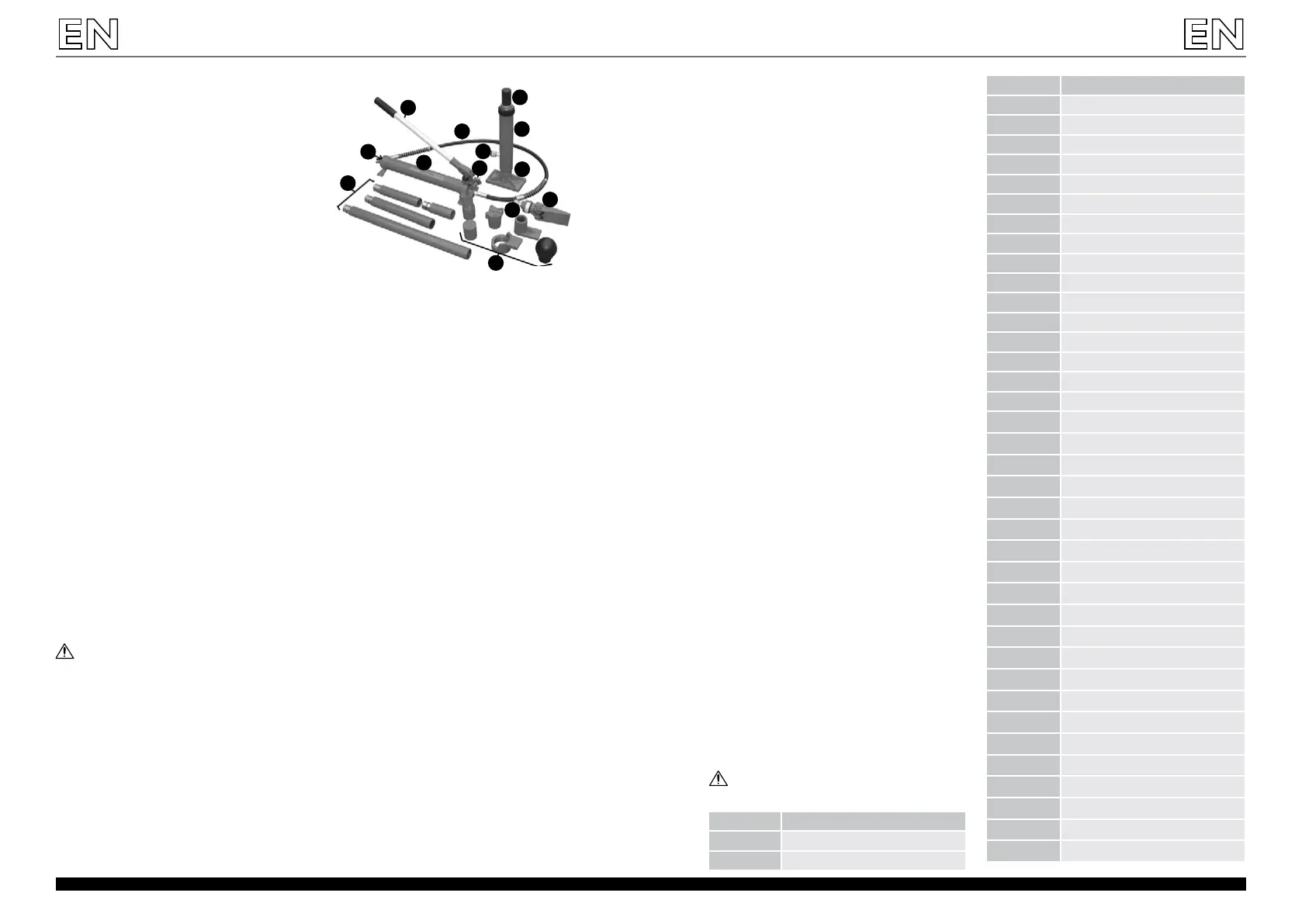
1. Hydraulic pump
2. Pump lever
3. Hydraulic hose
4. Hydraulic hose port
5. Actuator piston rod
6. Actuator
7. Actuator base
8. Expander
9. Attachments
10. Pipe extensions
11. Oil ller
12. Vent valve
3.2. PREPARING FOR USE
Remove the dust arresting cap from the hydraulic hose end
and then, connect the hose end to the hydraulic hose port
(4) in the actuator or the expander.
Make sure that the connections are carried out properly
and tight:
• close the vent valve and carry out several movements
with the lever; no air leakages can be heard.
3.3. DEVICE USE
Operation
1. Make sure that the vent valve (12) is closed, otherwise
close it by turning clockwise.
2. The hydraulic pump (1) can operate in horizontal or
vertical position. When in vertical position, set the
pump so as the hydraulic hose port is at the bottom.
3. If the actuator (6) is used, place it on the stable,
even substrate and centrally under the element to
be lifted. Choose one of the attachments (9), as
appropriate, and put it onto the piston rod (5).
4. If the expander (8) is used, place it in the slot between
elements to be expanded.
5. The device has the pipe extensions (10) to adapt the
actuator height to the user’s needs. The extensions
are to be put onto the actuator piston rod. One of
the attachments (9) can be put onto the extension
end.
Note: When using the pipe extensions, remember
that they should be put onto the piston rod from the
longest one up to the shortest one, i.e. the shortest
extension being put must be furthest from the
actuator.
Note: In case of use of all pipe extensions, the
maximum device load must not exceed a half of the
nominal value given in the technical data table.
6. To start lifting / expanding, carry out up-and-down
movements with the pump lever (2).
2
3
5
6
7
4
12
8
4
9
10
1
11
3.1. DEVICE DESCRIPTION
3. USE GUIDELINES
The Porta Hydraulic Jack is the device used to lift and
expand the vehicle body elements.
The user is liable for any damage resulting from
nonintended use of the device.
 Loading...