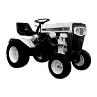
Series 700 Lawn Tractor
90
OCR Module
The Operator-Controlled Reverse System (OCR) used by MTD consists of a module. It take two functions or
steps to arm the OCR, per ANSI. These steps are:
1. Turn the key switch to the OCR position.
2. Press the orange triangle.
NOTE: A red LED will light up to notify the operator that the tractor is in mow in reverse mode.
When armed, the OCR module “disconnects” the reverse switch from the system. The module also monitors the
system. If an unsafe condition arises, the module will shut down.
NOTE: The starter safety circuit has no connection to the OCR module.
• The function of individual safety switches can be seen as providing information “inputs” to the OCR mod-
ule.
• The safety switch will turn the tractor off in an unsafe condition just as they always have. The only function
of the OCR module is to disconnect the reverse switch.
• The safety switches can now be checked from a central point on the mower. This makes life easier on the
technician, frequently making it unnecessary to connect to difficult to reach switches in the preliminary
stages of diagnosis.
The OCR module contains solid state electronic circuits. When diagnosing anything that is connected to the
OCR module, a high impedance test light or a high impedance digital multi-meter (DMM) must be used. The amper
-
age draw of a standard incandescent test light may over-burden some internal electronic circuits, burning out the
module.
NOTE: These tools are not outrageously expensive or exotic. High impedance test lights (Thexton model 125
is typical) can be purchased locally from stores like NAPA for under $30.00. Appropriate multi-meters can be
purchased for under $100.00, and are an invaluable tool for any competent technician.
• It is typical when industries shift from electromechanical to electronic controls that diagnosis shifts from
tracing through a number of independent circuits to checking the in-puts to and out-puts from a central
processor. This is similar to, but much less complex than the transition that the auto industry made with
the conversion to fuel injection in the 1980s.
• The next part of this section gives a detailed description of the electrical components on this mower, their
function in the system, and their physical location on the mower. Armed with this information and the
proper tools, a technician should be able to efficiently diagnose most electrical problems.
7-pin verses 8-pin module
When the OCR was first introduced for the 2005
model year, the module only had 7-pin in the harness con
-
nector. In 2006, an eight pin was added to the module. The
eight pin is grounded and help protect the module from
system noise. In addition to the pin, the afterfire solenoid’s
power was moved from the alternator to the A1 wire of the
key switch. The alternator is now wired to the battery feed
to the key switch.
See Figure 7.1.
Figure 7.1
8-pin module
7-pin module
Pin missing
FOR DISCOUNT PARTS CALL 606-678-9623 OR 606-561-4983
www.mymowerparts.com
 Loading...