Model 493.02 Controller Service
Calibrating a Force Sensor
Calibration
158
6. Determine the shunt calibration resistor from the following table:
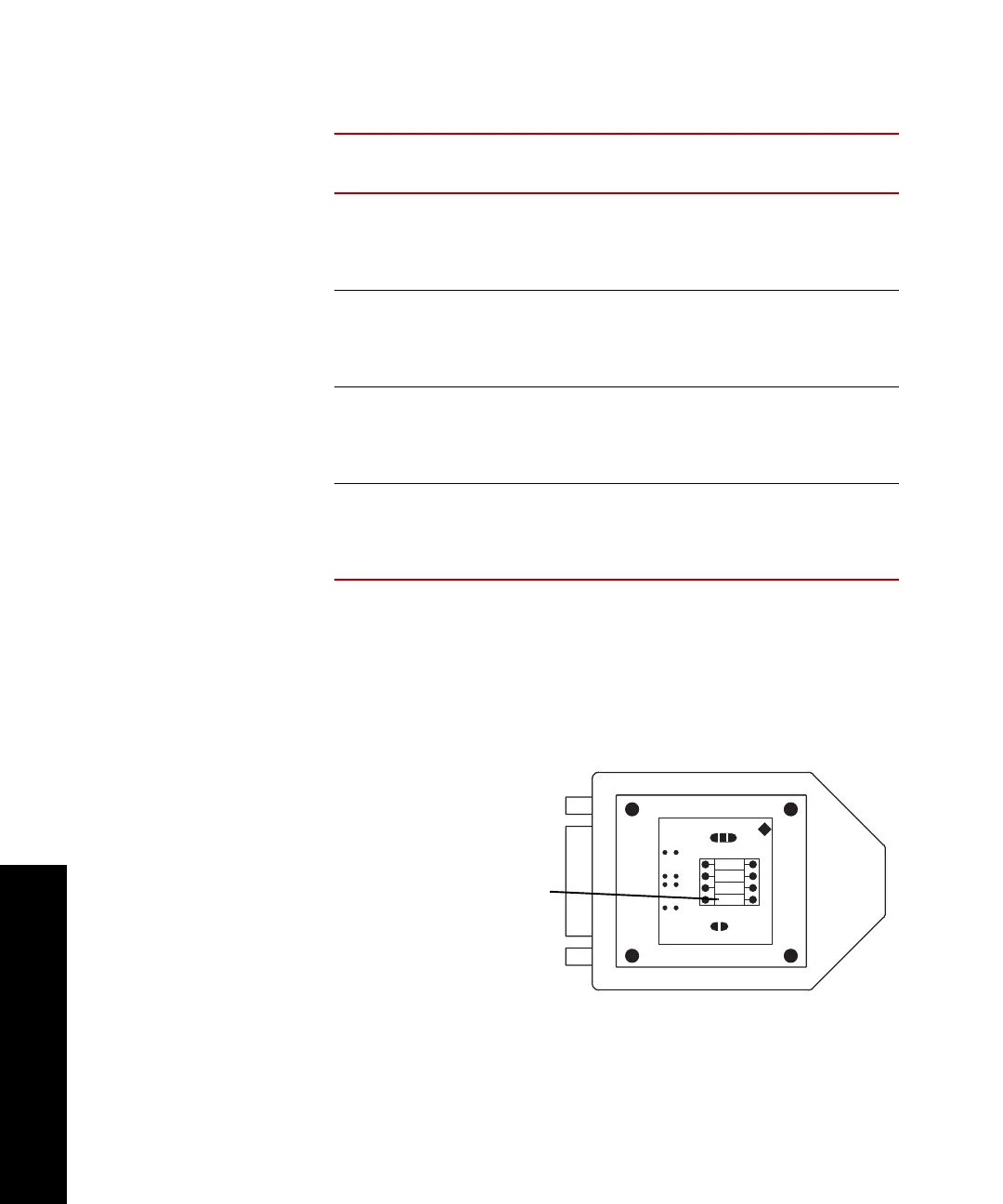
7. If you have sensor cables with optional transducer ID modules,
complete the following procedure. If not, proceed to Step 8.
Install the shunt calibration resistor into the R9 location of the
sensor ID module. The sensor identification cartridge is molded
into the sensor cable.
B
RIDGE
R
ESISTANCE
SENSITIVITY RANGE
(% FULL SCALE)
R
ESISTOR
V
ALUE
350 Ω 2 mV/V 100%
50%
20%
10%
49.9 k
100 k
249 k
499 k
350 Ω 1 mV/V 100%
50%
20%
10%
100 k
200 k
499 k
1000 k
700 Ω 2 mV/V 100%
50%
20%
10%
100 k
200 k
499 k
1000 k
700 Ω 1 mV/V 100%
50%
20%
10%
200 k
402 k
1000 k
2000 k
l
W1
W2
1
2
3
SC
R6
R7
R8
R9
Solder the shunt cal
resistor here
 Loading...