Calibrating a Force Sensor
Model 493.02 Controller Service
Calibration
159
8. If you do not have transducer ID modules on your sensor cables,
install the shunt calibration resistor as follows:
A. Select the appropriate shunt calibration resistor.
B. Bend the resistor leads 90º for a 0.3 inch separation.
C. Cut the resistor leads 0.12 inch from the bend.
D. Insert the resistor into the connector solder cups and solder.
E. Complete and attach a shunt calibration label as specified on
the 493.40/41 Carrier I/O Shunt Calibration Kit (MTS PN 100-
028-185).
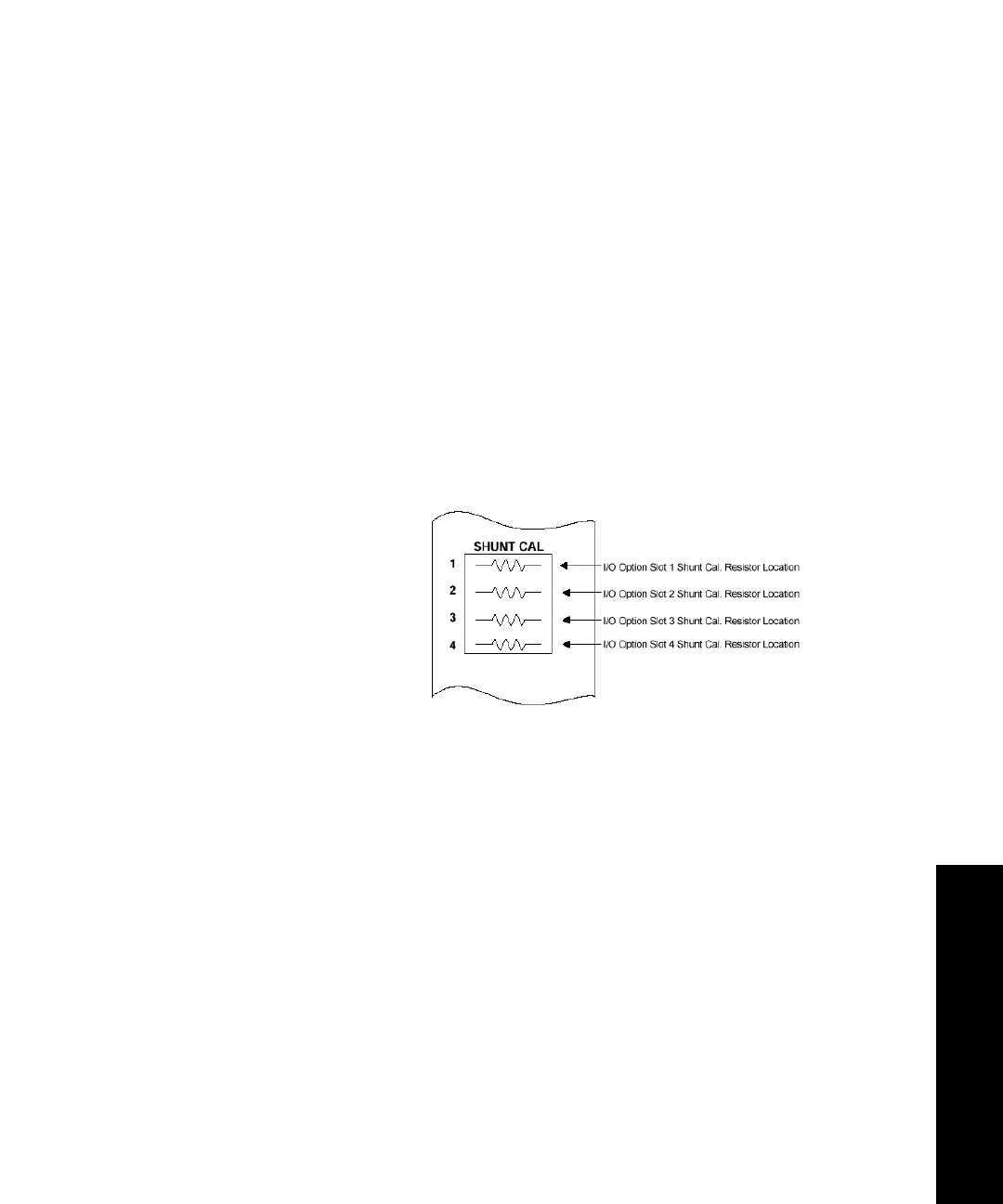
F. Install the shunt cal resistor/connector assembly into the
appropriate slot of the SHUNT CAL connector on the front
panel of the appropriate I/O Carrier Module.
9. Verify that force is still zero.
While it is unlikely, it is possible for the force signal to change
when the control mode changes. If it does:
Stand-Alone— Click Auto Offset on the Offset/Zero submenu
to zero the force output. Path: Setup > Force > Offset/Zero >
Auto Offset
Automated— Click Auto Offset on the Offset/Zero tab (Inputs
panel) to zero the force output.
 Loading...