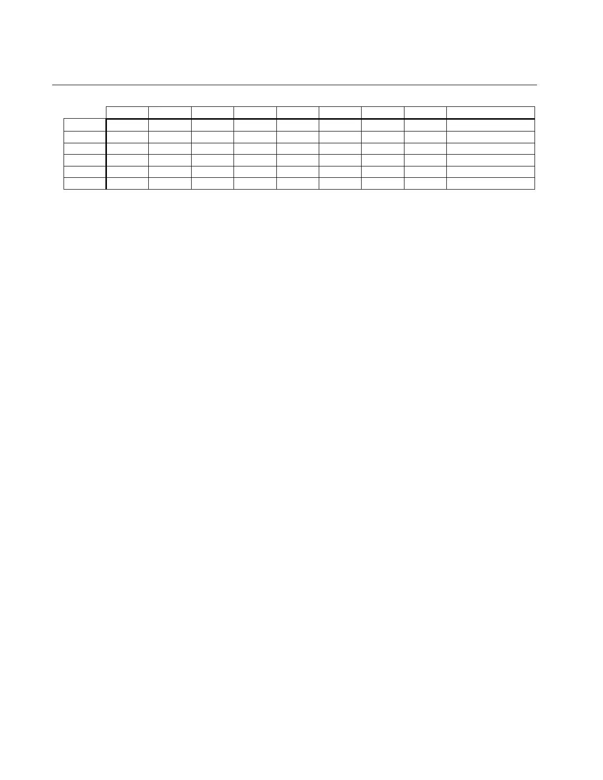
24
Default DIP Switch Settings
1 2 3 4 5 6 7 8 Comment
SW1
OFF OFF OFF OFF OFF OFF OFF OFF Lead/Lag
SW2
ON OFF ON OFF ON OFF ON OFF 12-bit mode
SW3
ON ON OFF OFF OFF OFF OFF ON TAC
S2
OFF ON ON ON I/O
S3
ON ON ON OFF Commutation
S4
OFF OFF ON ON Encoder (1024L)
SW1 determines the lead lag compensation networks, and is usually only modified to
achieve stability on high inertia loads.
SW2 is used to alter the operation of the R-D converter and is preset to the 12-bit mode.
This switch setting is only altered to achieve higher line density simulated encoder
selections or higher TAC gradients.
SW3 is used to alter the TAC gradient and works in conjunction with SW1 to achieve
stability on high inertia loads.
S2 switches 1-2 are used to determine the commutation of motors and are set for 6-pole
operation. When S2 switch 3 is ON (default), torque linearization to sine wave motors is
provided. When S2 switch 3 is OFF, torque linearization is not provided; this is typical for
trapezoid wound motors. S2 switch 4 can be used to invert the fault output to be normally
ON instead of OFF.
S3 is available to configure the operation of the I/O.
S4 is available to select the simulated encoder line density. The default setting is 1024
lines.
 Loading...