SP
ECIF
ICATIONS
Phys'ica'l Sjze:
5 inches wide
by 4
inches deep overall by 1.13 inches
thick
Connections:
I 24
p'in
edge
connector, I
12
pin
edge connector, 1
set of
24
edge
fingers, and one
set
of
12 edge
f ingers.
All
s'ignals are
fed through
frqn
the edge connectors to
the corresponding
edge
fingers.
DAC section:
B bits, offset
binary
encoded,
typ'ica1 1/4 LSB linearity,
guarenteed
monoton'ic, 5 vol
t
swi
ng, 6.25K output
impedance, 5
vol
t
supply
'is
filtered
and used as
the
reference voltage.
Fil ter section:
6
po1es,
0.5dB Chebyshev
response,
cutoff
f
requency
'is
3.5kHz.
Po,ver
anp
sect
j
on:
power
output: 150MW
jnto
1.6 ohms,
300MW
into 8
olms, 500fvlW
'into
4
ohms.
Amp'l
if
jer
response
is
flat wjthin 3dB frqn 30 to ZAkHz
wjth
an
8
ohm
load. Distortjon at full
power
output
into
B
ohms
at
lkHz
is less than &.
Porver requ'irements:
Single
+5
volt
supply.
Ripple and noise within the aud'io
range should be
less
than
2S4V.
Pover Consumption:
Quiescent
current
drain is less than 50MA. Worst
case
drain
at
f
ul
I
power,
4
ohr
I
oad,
an
d
square wave output i s 30ft1A .
Signal
loading: Less
than L0uA
and
10pF load'ing on
the 8 b'inary inputs.
CBz
input
is
loaded
by
240<
to
ground.
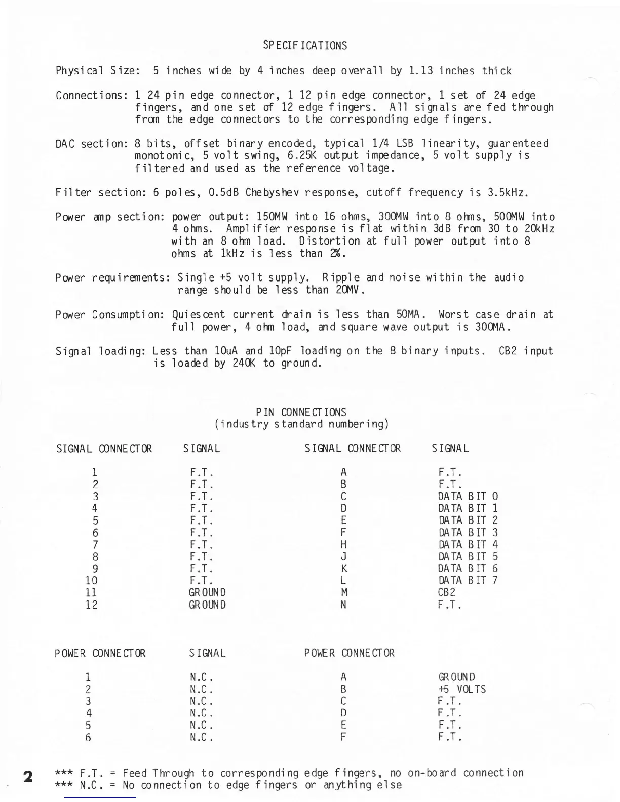
P IN
CONNEgTIONS
(
i ndustry standard numberi ng)
SIGNAL
CONNEffM
1
2
3
4
5
6
7
8
9
t0
11
I2
S IGNAL
F.T
.
F.T .
F.T
.
F.T
.
F.T
.
F.T.
F.T
.
F.T.
F.T
.
F.T .
GROI,FID
GROLT{D
S IS'IAL CONNETTOR S IS{AL
F.T.
F.T
.
DATA B IT O
DATA B IT 1
DATA B IT 2
DATA B IT 3
DATA B IT
4
DATA B
IT
5
DATA
B
IT 6
DATA B
IT
7
cB2
F.T.
GR, OUN
D
+5
VOLTS
F
.T.
F
.T.
F.T.
F.T.
A
B
D
E
F
H
J
K
L
M
N
CONNE
ffOR
A
B
c
D
E
F
POWER
CONNECTOR
***
F.T.
***
N.C
.
S
IGNAL
POWER
N.C .
N.C
.
N.C
.
N.C
.
N.C
.
N.C
.
1
I
2
3
4
5
6
2
Feed Through to
correspondi
ng edge
f ingers,
no on-board connect'ion
No connection
to edge
fingers
or
anything else
 Loading...