D. Check the condition of the
starting control circuits and
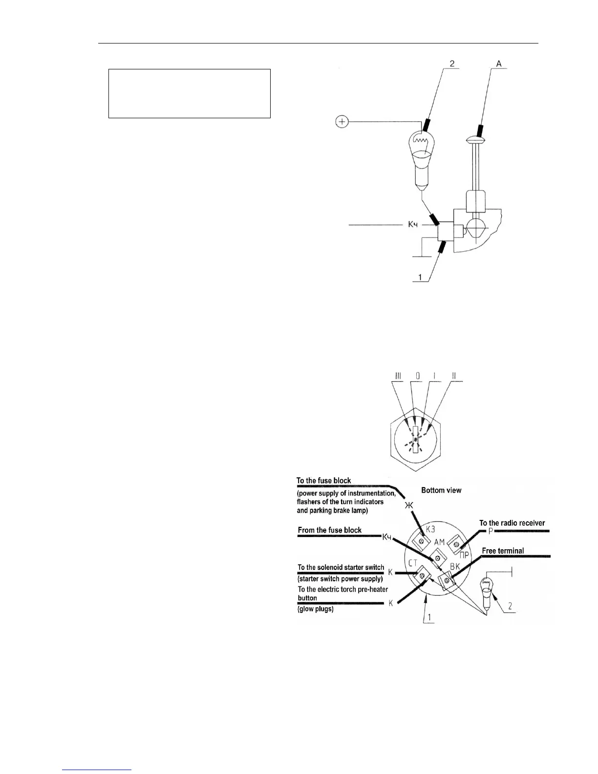
instruments:
a) Remove the side pieces of the
dashboard;
b) Check the operability of the
starter switch (SA6) by connecting
one wire of the test lamp to the
body and another wire to the
switch terminals in turn (Fig.8 and
9):
“+” – wire “Кч”;
“СТ” or “30” – wire “К” (the key
shall be in the position “II”);
In both cases, the test lamp shall
be lit.
Fig. 7. Checking the operation of the starter interlock switch.
1 – interlock switch; 2 – test lamp;
2 – “А” is the neutral position of the gearbox lever.
Top view
Fig.8. Checking the operability of the starter switch (SA6). For
the instrumentation dashboard 80-3805010-Д1.
1 – Starter switch;
2 – Test lamp.
Starter switch key position:
“О” – OFF; “I” – the measuring
instrumentation, pilot lamp blocks,
flashers of the turn indicators and
and parking brake pilot lamp, radio
receiver, key of the electric torch
pre-heater (or glow plugs) of the
engine starting aid system
(terminals “K3”, “ПР”, “ВК” or “58”,
“19”, “15”) are energized;
“II” – the consumers of the position
“I” (except for the radio receiver,
“ПР” or “15”), starter solenoid
switch and winding of the electric
torch pre-heater through the button
of the electric torch pre-heater
(when being released, the key
returns to the position I) (terminals
“К3”, “ВК”, “СТ” or “58”, “15”) are
energized;
“III” – the radio receiver is
energized (terminal “ПР ” or “15”).
c) Check the integrity of the circuits
and application of the voltage to
the terminals of the starter
solenoid switch (K7) (Fig. 10):
• check one wire of the test lamp to
the body and another one in turn to